Fuel hose assembly for in-flight fuelling of aircraft

A hose assembly, aerial refueling technology, used in aircraft parts, hoses, pipes/fittings/fittings, etc., which can solve the problem of unlikely safety certification, the IFR system is not suitable for large civil aircraft, and the lateral movement of the hose is large. and other problems, to achieve high fuel pressure and flow rate, high longitudinal stiffness and stability, space saving effect

Pending Publication Date: 2021-05-14
БРУЛИК ЛТД
View PDF7 Cites 0 Cited by
  • Summary
  • Abstract
  • Description
  • Claims
  • Application Information

AI Technical Summary

Problems solved by technology

This suggests a need for a longer hose, however this can be problematic as the "whipping" effect of the length causes the hose to move more laterally in the air
[0008] For these reasons at least the type of IFR system used by military operators does not appear to be suitable for large civilian aircraft and is unlikely to be certified safe for commercial airline operations

Method used


Image

  • Fuel hose assembly for in-flight fuelling of aircraft
  • Fuel hose assembly for in-flight fuelling of aircraft
  • Fuel hose assembly for in-flight fuelling of aircraft

Examples


Embodiment Construction

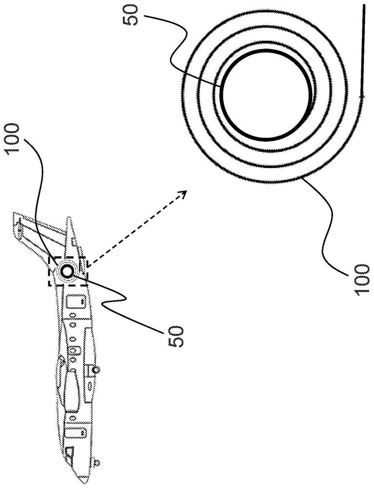
[0040] figure 1 A fuel dispenser is shown comprising a fuel hose assembly 100 coiled on a motorized hose drum unit 50 and provided with a fuel supply carried by the dispenser.

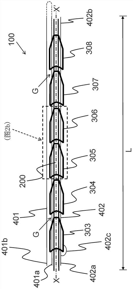
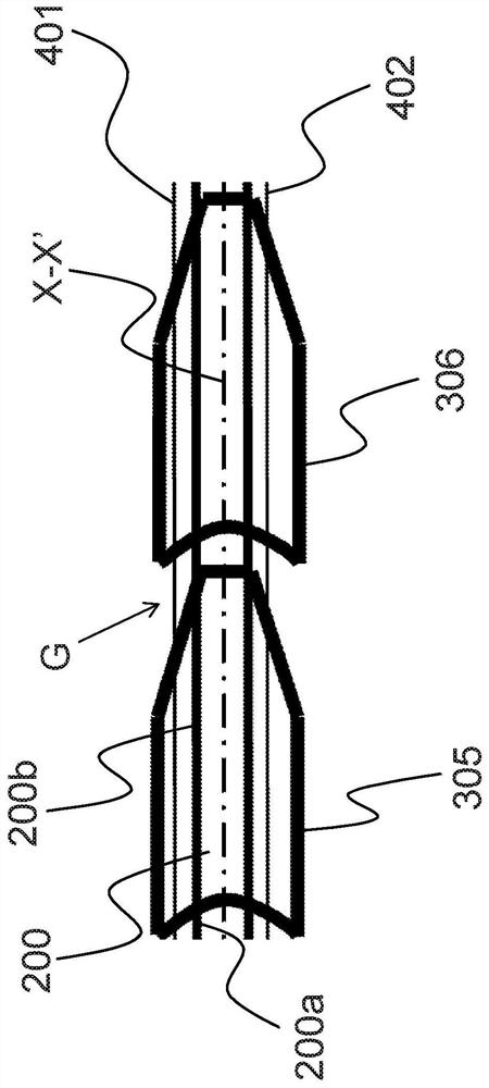
[0041] Figure 2a An exemplary portion of fuel hose assembly 100 is shown having a length L and a longitudinal axis XX′. The fuel hose assembly 100 includes an elongated tubular core 200, a plurality of rigid segments 301-311, and first and second control strands 401, 402 and auxiliary strands (in Figure 2a Only one auxiliary rope 402c) is shown in . Rigid segments 301-311 are separated by gap G (spaced apart). It should be understood that in Figure 2a Only some of the rigid segments 303 - 308 of the fuel hose assembly 100 are visible in FIG. 1 because only a portion of the fuel hose assembly 100 is shown. For ease of understanding the following description, Figure 2b show Figure 2a An enlarged detail of a portion of the fuel hose assembly 100 .

[0042] The tubular core 200 includes an inn...


PUM


Abstract

A fuel hose assembly for inflight fuelling of aircraft comprises: a flexible inner tube for conveying fuel under pressure; an outer cover comprising a plurality of rigid parts; and an actuator configured to move the rigid parts lengthwise along the flexible inner tube. The rigid parts are movable by the actuator to provide continuous lengthwise cover over the flexible inner tube, so as to be able to resist radial expansion of the flexible inner tube when the flexible inner tube is pressurised. The rigid parts are further movable by the actuator to uncover lengthwise portions of the flexible inner tube between the rigid parts, so as to allow bending of the flexible inner tube when the flexible inner tube is unpressurised.

Description

Background technique [0001] The present invention relates to fuel hose assemblies for in-flight (re)fuelling of aircraft. [0002] In-flight refueling (IFR) involves the transfer of fuel from one aircraft ("tanker") to another aircraft ("recipient") during flight. IFR (also known as in-flight refueling or air-to-air refueling) has become a well-established method for extending the range or cruise time of military aircraft (or increasing takeoff payload). Typically, the tanker is based on an airliner that has been redesigned or modified specifically for refueling operations, while the receiver aircraft is usually a fighter, or possibly a bomber or reconnaissance aircraft. [0003] Today, two different IFR methods are widely used: flying boom and probe-and-drogue. [0004] The aerial telescoping sleeve is attached to the rear of the tanker and consists of a rigid, telescoping and hinged tube with a nozzle at one end. The telescopic sleeve includes flight control surfaces that...

Claims


Application Information

Patent Timeline
Patent Type & Authority Applications(China)
IPC IPC(8): B64D39/04
CPCB64D39/04F16L11/12F16L11/18B67D7/0401
Inventor 詹姆斯·皮特曼
Owner БРУЛИК ЛТД
Why Eureka
Try Eureka