Roller fastening arrangement

A fastening and roller technology, applied in the field of roller fastening devices, can solve the problems of no longer being able to disassemble, difficult disassembling of the contact disc, disassembling of bolts, etc.

Active Publication Date: 2021-05-14
TRUETZSCHLER GRP SE
View PDF5 Cites 0 Cited by
  • Summary
  • Abstract
  • Description
  • Claims
  • Application Information

AI Technical Summary

Problems solved by technology

However, due to the rotation of the rollers during operation, the bolts can hardly be removed for changing the rollers or can no longer be removed at all
The so-called breakaway torques for removal have increased over time in such a way that the removal of the contact disks is rather difficult and the bearings of the corresponding contact disks are partially damaged so that the bearings have to be replaced

Method used


Image

  • Roller fastening arrangement
  • Roller fastening arrangement
  • Roller fastening arrangement

Examples


Embodiment Construction

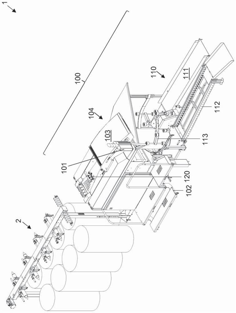
[0024] figure 1 An arrangement 1 with a creel 2 and a downstream draw frame 100 is shown in a typical arrangement.

[0025] The creel 2 is constructed in a known manner and will not be described again.

[0026] Furthermore, the draw frame 100 has a coiling device 110 on the delivery side. In the example shown, the coiling device 110 comprises a can rail 111 for full cans and a preferably driven can guide 112 which moves the empty cans to the actual, unmarked coil on the can changer of the bar device 110. The can changer has, for example, a can mover 113 in a known manner. On the side of the draw frame 100 there is an operating platform 102 . An operator terminal 101 is located here at one end of an operator platform 102 . Furthermore, a drafting mechanism cover 103 can be seen, which covers the drafting section 104 in a known manner. Upstream of the drafting section 104 in the direction of transport of the fiber sliver, there is a measuring system 120 with two unmarked m...


PUM


Abstract

An arrangement (120) has a clamping portion (124) and a roller portion (126, 131, 127) having a drive portion (131), receiving portion (126b) and fastening portion (123). The roller portion (126) is operatively connected in terms of rotation to a drive element. The receiving portion (126b) receives a roller (125) and is arranged behind the drive portion (131) as seen along the axis of rotation of the roller portion (126). As seen in this direction, the fastening portion (123) is arranged behind the receiving portion (126b) and has a fastening opening (123a) that is open towards a clamping side remote from the receiving portion (126b), extends in the direction of the receiving portion (126b) and is arranged away from the axis of rotation. The clamping portion (124) is placed on the receiving portion (126b) from the clamping side and has, for each fastening opening (123a), an associated through-opening (122a), which is aligned with this fastening opening (123a) as seen in the direction. A fastening element (3) engages, from a fitting side, through the associated through-hole (122a), retaining the clamping portion (124) on the roller (125), into the associated fastening opening (123a) in a force- and/or form-fitting manner. The axes of rotation of the roller portions (126) of two arrangements (120) of a measuring system (120) of a textile machine (100) extend parallel to one another and are spaced apart from one another as seen in the direction.

Description

technical field [0001] The invention relates to the fastening of rollers, in particular measuring rollers of a drafting mechanism. Background technique [0002] Such rollers are constructed independently at one end. The roller is thus fixed freely rotatable about its axis of rotation, usually by a clamping sleeve being slipped over from the free end and fixed by means of a centrally arranged screw. However, the rotation of the rollers during operation means that the bolts can hardly be removed for changing the rollers or can no longer be removed at all. The so-called breakaway torques for removal have increased over time in such a way that the removal of the contact discs is rather difficult and the bearings of the respective contact discs are partially damaged so that the bearings have to be replaced. Contents of the invention [0003] The object of the present invention is to counteract said disadvantages. [0004] Said object is solved by the subjects of the independ...

Claims


Application Information

Patent Timeline
Patent Type & Authority Applications(China)
IPC IPC(8): D01G31/00D01H13/32B65H27/00F16C13/00
CPCD01H13/32D01G31/006F16C13/00F16C2340/00F16C2340/24F16C2340/18
Inventor 托马斯·施密茨
Owner TRUETZSCHLER GRP SE
Why Eureka
Try Eureka