Sludge discharge system

A technology of sludge discharge pipe and baffle, which is applied in the feeding/discharging device, chemical instrument and method, separation method, etc. And other issues

Active Publication Date: 2021-05-18
TAIZHOU UNIV
View PDF6 Cites 1 Cited by
  • Summary
  • Abstract
  • Description
  • Claims
  • Application Information

AI Technical Summary

Problems solved by technology

However, in the mud accumulation area of ​​the sedimentation tank, there is an inclined platform surrounded by a V-shaped mud accumulation tank, which occupies a large amount of space in the mud accumulation area, reduces the space for storing mud in the mud accumulation area, and increases the number of mud discharges; in addition , the perforated mud discharge pipe is provided with a large number of mud discharge holes along the direction of the mud accumulation tank, so that the hydraulic conditions between the mud discharge holes are greatly different, resulting in the blockage of the mud discharge holes, and the mud accumulation in some areas of the mud accumulation area cannot be smoothly For discharge, the inclined plate needs to be disassembled, and the mud accumulation cannot be removed by cleaning

Method used


Image

  • Sludge discharge system
  • Sludge discharge system
  • Sludge discharge system

Examples


Embodiment Construction

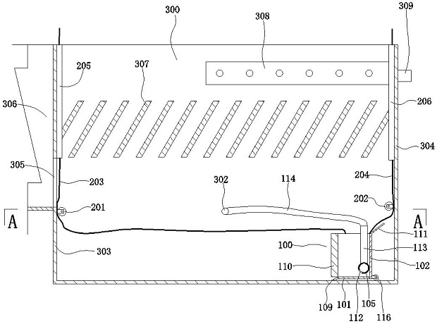
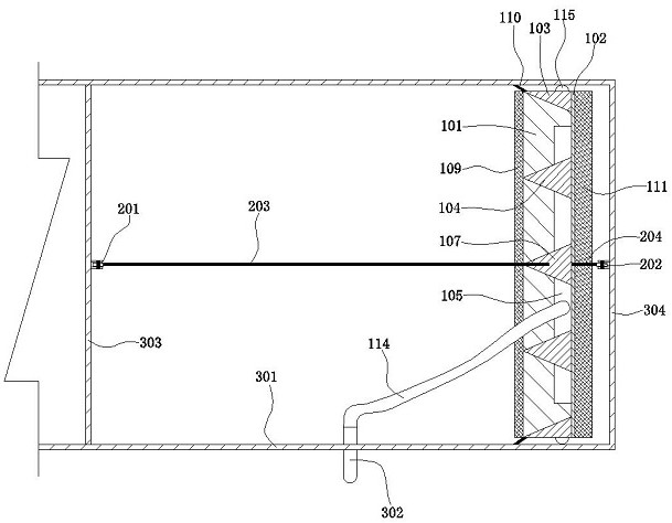
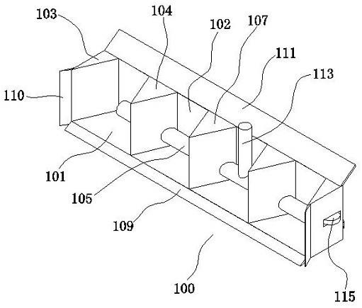
[0012] Below in conjunction with accompanying drawing, the present invention will be further described with specific embodiment, see figure 1 —4.

[0013] A mud discharge system includes a driving mechanism and a mud discharge mechanism 100 . The mud discharge mechanism 100 includes a bottom plate 101 , a back plate 102 , a side plate 103 , a partition 104 and a mud discharge pipe 105 . One side of the bottom plate 101 is fixedly connected to one side of the back plate 102 , and two adjacent side surfaces of the bottom plate 101 and the back plate 102 are fixedly connected to two sides of two side plates 103 at the same time. A partition 104 is arranged between the two side panels 103, and the partition 104 is fixedly connected to the bottom panel 101 and the back panel 102 at the same time, and the partition 104 and the side panels 103 are triangular prisms. A “eight”-shaped opening 106 is formed between the side plate 103 and the partition 104 , and a “eight”-shaped openin...


PUM


Abstract

The invention discloses a sludge discharge system, and belongs to the technical field of sedimentation tanks. The sludge discharge system comprises a driving mechanism and a sludge discharging mechanism, the sludge discharging mechanism comprises a bottom plate, a back plate, side plates, a partition plate and a sludge discharging pipe, the bottom plate is connected with the back plate, the two side plates are arranged on the two sides of the bottom plate and the back plate, the partition plate is arranged between the two side plates, the partition plate is fixed to the bottom plate and the back plate, the partition plate and the side plates are triangular prisms, sludge scraping pieces are arranged on the side edges of the bottom plate and the side plates, and a sludge blocking piece is arranged on the top edge of the back plate. The sludge discharging pipe penetrates through the partition plate, a vertical pipe is arranged on the sludge discharging pipe, a sludge discharge hose is connected to the vertical pipe, the sludge discharge hose is connected with a sludge outlet pipe, a pulley is arranged on the side face of each side plate, a pulley is arranged on the lower portion of the side face of the back plate, a driving mechanism comprises a fixed pulley, two pull ropes and a sleeve, the fixed pulley and the sleeve are arranged on the side wall of a sedimentation tank, and the two pull ropes are fixed to a sludge discharge mechanism. The pull ropes penetrate through the fixed pulley and the sleeve and are arranged at the top of the sedimentation tank. The system occupies a small space of a sludge accumulation area, and the sludge discharge operation frequency is reduced; and the hydraulic sludge discharge condition of perforation is improved.

Description

technical field [0001] The invention relates to a mud discharge system of an inclined plate sedimentation tank, in particular to a mud discharge system suitable for an inclined plate sedimentation test device. Background technique [0002] There is a very shallow sedimentation tank between every two parallel inclined plates in the inclined plate sedimentation tank. Make the treated water and the settled sludge move and separate in the shallow sedimentation layer. The inclined plate sedimentation tank uses the principle of "shallow sedimentation" to shorten the sedimentation distance of particles, thereby shortening the sedimentation time, and increasing the sedimentation area of ​​the sedimentation tank, thereby improving the treatment efficiency and reducing the floor space, so it is widely used. Because of its simple structure and convenient operation, the perforated mud discharge pipe is often used as the mud discharge system of the inclined plate sedimentation tank. Ho...

Claims


Application Information

Patent Timeline
Patent Type & Authority Applications(China)
IPC IPC(8): B01D21/24B01D21/00
CPCB01D21/245B01D21/0045
Inventor 王志勇王春凌谭浩强王先兵刘树元
Owner TAIZHOU UNIV
Why Eureka
Try Eureka