
Gear machining deburring machine

A deburring machine and gear technology, applied in the field of gear processing, can solve problems such as low efficiency

Inactive Publication Date: 2021-05-18
蚌埠美域装饰工程有限公司
View PDF0 Cites 3 Cited by
  • Summary
  • Abstract
  • Description
  • Claims
  • Application Information

AI Technical Summary

Problems solved by technology

[0003] The purpose of the present invention is to solve the shortcoming of low efficiency in the prior art, and propose a kind of gear processing and deburring machine

Method used


Image

  • Gear machining deburring machine
  • Gear machining deburring machine
  • Gear machining deburring machine

Examples


Embodiment Construction

[0020] The following description serves to disclose the present invention to enable those skilled in the art to carry out the present invention. The preferred embodiments described below are only examples, and those skilled in the art can devise other obvious variations.

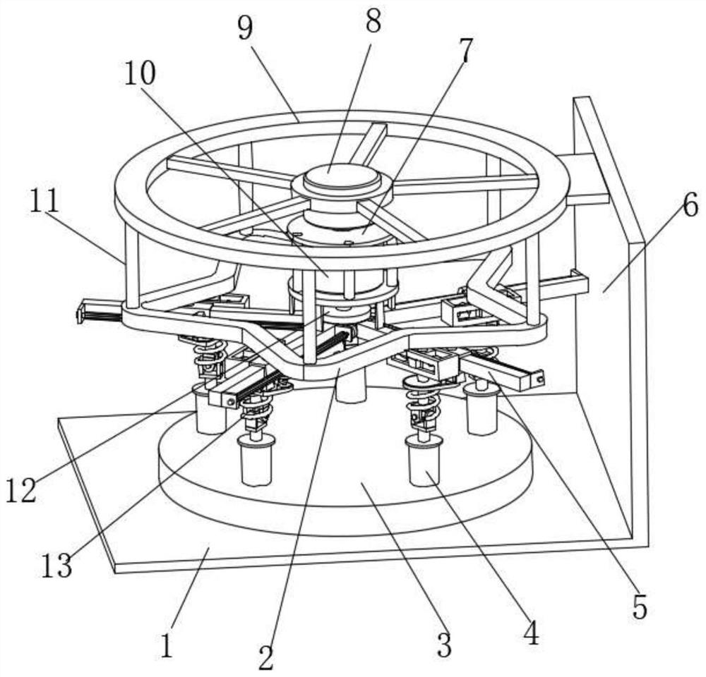
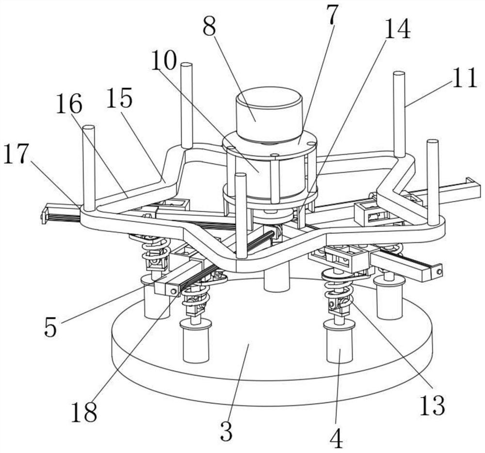
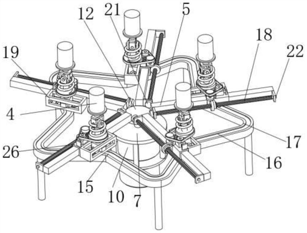
[0021] Such as Figure 1-Figure 5 The shown gear processing and deburring machine includes a top frame 9 on which a first motor 8 is fixed, the output shaft of the first motor 8 is connected to a mounting frame 7, and a second motor 10 is fixed on the mounting frame 7 , the end of the output shaft of the second motor 10 is connected with a drive gear 12, and the mounting frame 7 is fixedly connected with a plurality of slide bars 5 through a fixed plate 14, and the slide bars 5 are in a ring array around the drive gear 12, and the two ends of the slide bar 5 are vertically fixed There is a support plate 30, and a rotating shaft 22 is rotatably connected between the two supporting plates 30. One end of the r...


PUM


Abstract

The invention relates to the technical field of gear machining, in particular to a gear machining deburring machine. The gear machining deburring machine comprises a top frame, a first motor is fixed to the top frame, an output shaft of the first motor is connected with a mounting frame, a second motor is fixed to the mounting frame, the end of an output shaft of the second motor is connected with a driving gear, the mounting frame is fixedly connected with a plurality of sliding rods through fixing plates, the sliding rods are annularly arrayed around the driving gear, supporting plates are perpendicularly fixed to two ends of each sliding rod, a rotating shaft is rotationally connected between each two supporting plates, one end of each rotating shaft is coaxially connected with a transmission gear, the transmission gears are meshed with the driving gear, the middle of each rotating shaft is provided with a spline shaft coaxially arranged with the rotating shaft, each sliding rod is sleeved with a sliding sleeve in sliding fit with the sliding rod, a mounting plate is fixed to each sliding sleeve, and a rotating ring is rotationally mounted on each mounting plate. With the gear machining deburring machine, the working efficiency of gear deburring machining can be improved.

Description

technical field [0001] The invention relates to the field of gear processing, in particular to a gear processing and deburring machine. Background technique [0002] During the processing of gears, it is inevitable that burrs will be left on the processing surface. In the prior art, manual deburring machines are used for cleaning, which is less efficient. Moreover, for large characteristic gears, manual cleaning requires more time, which is not conducive to Technological development. Contents of the invention [0003] The object of the present invention is to solve the shortcoming of low efficiency in the prior art, and propose a gear processing and deburring machine. [0004] In order to achieve the above object, the technical solution adopted in the present invention is: a gear processing and deburring machine, including a top frame, a first motor is fixed on the top frame, and a mounting frame is connected to the output shaft of the first motor, so The mounting frame ...

Claims


Application Information

Patent Timeline
Patent Type & Authority Applications(China)
IPC IPC(8): B24B9/00B24B47/12B24B41/02B24B41/00
CPCB24B9/00B24B41/00B24B41/02B24B47/12
Inventor 刘光亮
Owner 蚌埠美域装饰工程有限公司
Learn More