
Gas cushion filling device and material suction filling method

A filling equipment and air cushion technology, which is applied in the field of air cushion filling equipment and suction filling, can solve the problems of small filling amount, unsatisfactory use requirements, incomplete filling, etc.

Pending Publication Date: 2021-05-18
TIANJIN WEIDI SCI & TECH CO LTD
View PDF0 Cites 0 Cited by
  • Summary
  • Abstract
  • Description
  • Claims
  • Application Information

AI Technical Summary

Problems solved by technology

[0005] The object of the present invention is to provide a kind of air cushion filling equipment and suction filling method, solve the problem that most of the existing air cushion filling equipment is filled by injection, and the filling process is to put the sponge first, and then inject the material. However, the filling speed is slow, the raw materials will flow out from the side of the air cushion during the filling process, there is a situation of incomplete filling, the filling volume is small, and it is impossible to fill and inject materials with high viscosity, which is not satisfactory for use. need

Method used


Image

  • Gas cushion filling device and material suction filling method
  • Gas cushion filling device and material suction filling method
  • Gas cushion filling device and material suction filling method

Examples


Embodiment Construction

[0030] The following will clearly and completely describe the technical solutions in the embodiments of the present invention with reference to the accompanying drawings in the embodiments of the present invention. Obviously, the described embodiments are only some, not all, embodiments of the present invention. Based on the embodiments of the present invention, all other embodiments obtained by persons of ordinary skill in the art without creative efforts fall within the protection scope of the present invention.

[0031] In the description of the present invention, it should be understood that the terms "upper", "middle", "outer", "inner" and the like indicate orientation or positional relationship, and are only for the convenience of describing the present invention and simplifying the description, rather than indicating or It should not be construed as limiting the invention by implying that a referenced component or element must have a particular orientation, be constructe...


PUM


Abstract

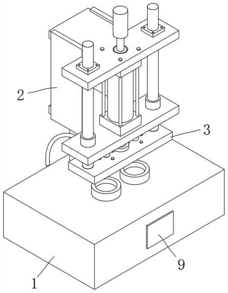
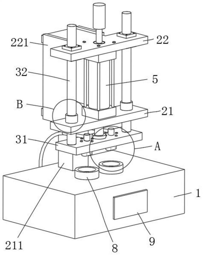
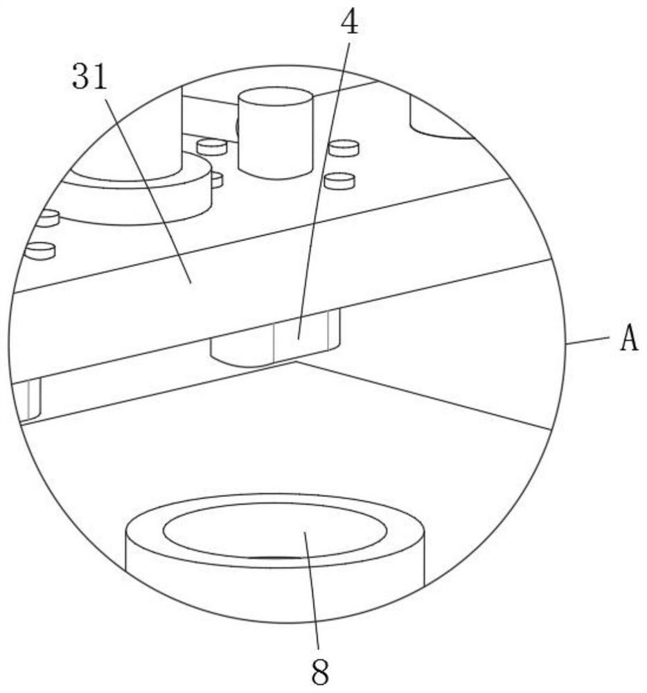
The invention discloses a gas cushion filling device and a material suction filling method, and relates to the field of filling equipment. The gas cushion filling device comprises a filling platform, the top of the filling platform is fixedly provided with a fixed platform, the bottom of the fixed platform is movably sleeved with a movable platform, material suction nozzles are fixed installed at the bottom of the movable platform, each material suction nozzle is provided with multiple small holes, and the small holes with different hole diameters and different numbers can be customized according to needs. A cylinder is fixedly installed in the center of the bottom of the fixed platform, the output end of the cylinder is fixedly connected with the movable platform, a communicating pipe is fixedly connected to the back of each material suction nozzle, a vacuum negative pressure bin is arranged on the back of the filling platform, and the end, away from the corresponding material suction nozzle, of each communicating pipe is fixedly connected with the vacuum negative pressure bin. The filling mode is material suction filling, a material body at the bottom of a gas cushion box is sucked to sponge through the negative pressure of the material suction nozzles, the filling amount is large, the filling speed is high, the volume production capacity is high, and the production efficiency is high.

Description

technical field [0001] The invention belongs to the technical field of filling equipment, and in particular relates to an air cushion filling equipment and a suction filling method. Background technique [0002] Air cushion liquid foundation is a must for nude makeup. Its function is to conceal blemishes, adjust skin tone, and hide pores. The product design is easy to carry, and you can quickly apply makeup and touch up makeup anytime and anywhere. The air cushion sponge is not a liquid foundation, but the product overflows when you press it lightly. It is this special way of existence that gives the air cushion liquid foundation a different product experience. [0003] During the production of air cushion foundation, it is necessary to add an air cushion sponge inside the air cushion box to fill the foundation liquid. Most of the current air cushion filling equipment is filled by filling. The filling process is to put the sponge first, and then inject the material. However,...

Claims


Application Information

Patent Timeline
Patent Type & Authority Applications(China)
IPC IPC(8): B65B3/14B65B39/00B67C3/08B67C3/26
CPCB65B3/14B65B39/00B67C3/08B67C3/2614
Inventor 马景利
Owner TIANJIN WEIDI SCI & TECH CO LTD
Learn More