
Linear continuous filling peristaltic pump

A peristaltic pump, linear technology, applied in the field of linear continuous filling peristaltic pump, can solve the problems of waste, reduce filling efficiency, energy waste, etc., to save filling time, increase filling volume, reduce installation volume effect

Pending Publication Date: 2021-12-10
CHANGSHA ZENITHSUN INTELLIGENCE QUANTITATIVE TECH CO LTD
View PDF0 Cites 0 Cited by
  • Summary
  • Abstract
  • Description
  • Claims
  • Application Information

AI Technical Summary

Problems solved by technology

During one cycle of the reciprocating motion of the roller, only the filling stroke squeezes the hose for filling, and the reset stroke is in the state of loosening the hose. As a result, the existing peristaltic pump filling system is only suitable for small filling volumes, and there is a The empty stroke is wasted, which not only increases the filling time interval, but also reduces the filling efficiency and causes energy waste, which limits the application range of peristaltic pumps to a certain extent

Method used


Image

  • Linear continuous filling peristaltic pump
  • Linear continuous filling peristaltic pump
  • Linear continuous filling peristaltic pump

Examples


Embodiment 1

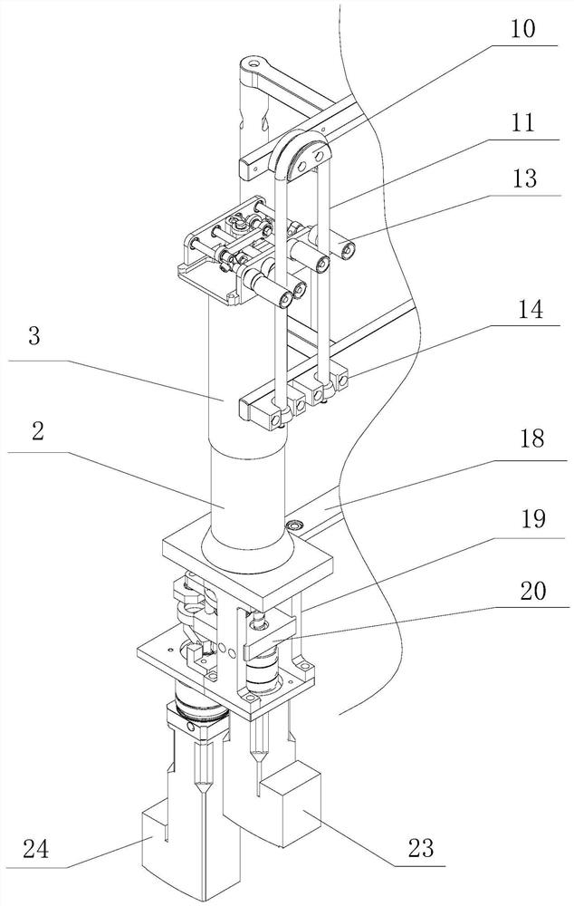
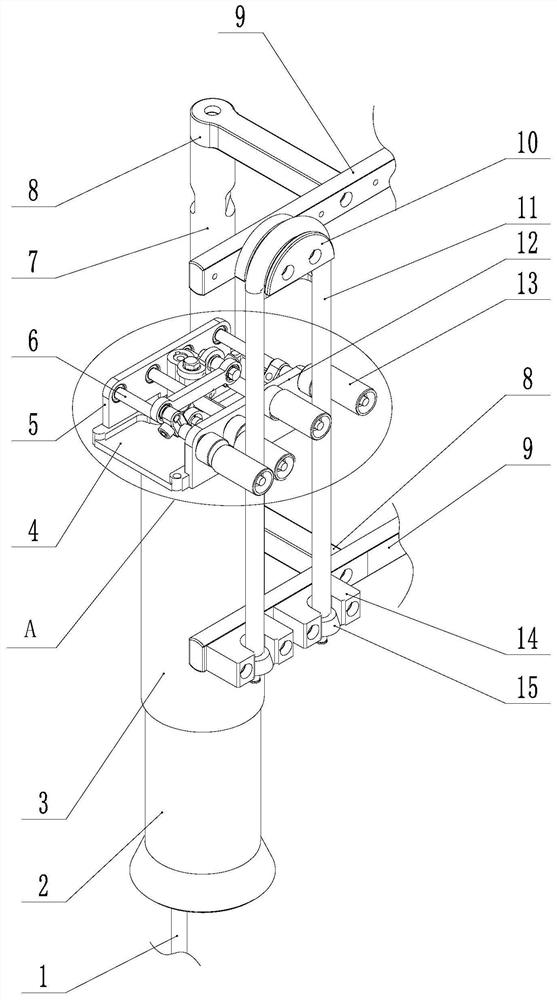
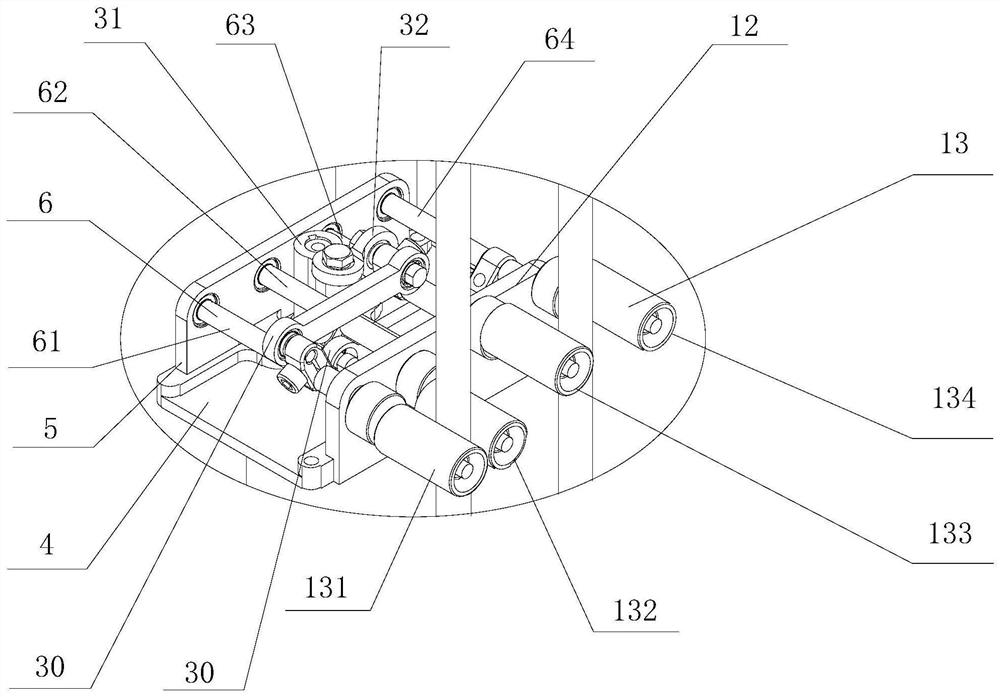
[0031] like Figure 1 to Figure 4As shown, a linear continuous filling peristaltic pump of the present invention includes: a pump body assembly, a pipeline assembly, a pressure tube assembly and a linear reciprocating assembly. The pipeline assembly includes a hose 11 and a hose bracket assembly. The hose bracket assembly is arranged on the side of the pump body. The middle part of the hose 11 is suspended on the top of the hose bracket assembly. The bottom end of the pipe bracket assembly is arranged in a straight line between the middle part and both ends of the flexible pipe 11 . Both the linear reciprocating assembly and the pressing tube assembly are installed on the pump body assembly, and the linear reciprocating assembly is used to drive the pressing tube assembly to perform linear reciprocating motion. In one cycle of the linear reciprocating movement of the compression tube assembly, the compression tube assembly first performs hose extrusion along the input end of ...

Embodiment 2

[0047] like Figure 5 As shown, the linear continuous filling peristaltic pump of the present invention has roughly the same structure and working principle as the linear continuous filling peristaltic pump in Embodiment 1, the difference is that the roller mounting shaft 6 includes the first roller mounting shaft 61 and the second roller installation shaft 62, the two ends of the first roller installation shaft 61 and the second roller installation shaft 62 are provided with rollers, that is, the two ends of the first roller installation shaft 61 are respectively provided with the second roller 132 and the second roller 132. Four rollers 134 , the first roller 131 and the third roller 133 are respectively provided at the two ends of the second roller installation shaft 62 . The first roller mounting shaft 61 and the second roller mounting shaft 62 are both eccentric shafts, and are connected to the spline shaft 1 through corresponding swing rod sleeves 31 , cross connecting r...

Embodiment 3

[0051] like Image 6 As shown, a linear continuous filling peristaltic pump of the present invention has substantially the same structure and working principle as the linear continuous filling peristaltic pump in Embodiment 1, the difference is that the roller mounting shaft 6 includes a first roller Installation shaft 61, the second roller installation shaft 62 and the third roller installation shaft 63, one end of three roller installation shafts is fixed on the rear seat 5, and the other end passes through the front seat 12 and is provided with rollers. That is, a first roller 131 is provided at the end of the first roller installation shaft 61 , a second roller 132 is provided at the end of the second roller installation shaft 62 , and a third roller 133 is provided at the end of the third roller installation shaft 63 . The hose 11 runs between the first roller 131 , the second roller 132 and the third roller 133 .

[0052] In this embodiment, the first roller mounting sh...


PUM


Abstract

The invention discloses a linear continuous filling peristaltic pump. The linear continuous filling peristaltic pump comprises a pump body assembly, a pipeline assembly, a pipe pressing assembly and a linear reciprocating motion assembly, wherein, the pipeline assembly comprises a hose and a hose support assembly, the hose support assembly is arranged on the side portion of a pump body, the hose is hung at one end of the hose support assembly, the input end and the output end of the hose are fixed to the other end of the hose support assembly, and the hose hanging portion and the two ends are linearly arranged; the linear reciprocating motion assembly and the pipe pressing assembly are both installed on the pump body assembly, and the linear reciprocating motion assembly is used for driving the pipe pressing assembly to do linear reciprocating motion; and in one cycle of reciprocating motion of the pipe pressing assembly, the pipe pressing assembly extrudes or loosens the hose from the hose input end to the hose hanging portion and from the hose hanging portion to the hose output end, so that continuous filling and metering of materials are achieved. The linear continuous filling peristaltic pump has the advantages of compact structure, high filling efficiency, stable metering and the like, and continuous material filling of the linear peristaltic pump is realized.

Description

technical field [0001] The invention mainly relates to the technical field of fluid filling pumps, in particular to a linear continuous filling peristaltic pump. Background technique [0002] At present, the multi-position mechanical filling pumps used in the field of fluid filling include plunger pumps, peristaltic pumps, syringe pumps and the like. Among them, peristaltic pumps are widely used in various industries due to their advantages of no pollution and better accuracy, including chemical industry, pharmaceutical industry, food filling industry and so on. In the linear peristaltic pump filling system, the hose is arranged in a straight line between the input end and the output end of the peristaltic pump. In order to meet the high requirements of fluid filling in terms of accuracy and stability, it is necessary to squeeze the hose through the roller during the operation of the peristaltic pump, just like pinching the hose with two fingers, the roller squeezes the hos...

Claims


Application Information

Patent Timeline
Patent Type & Authority Applications(China)
IPC IPC(8): F04B43/12F04B53/00
CPCF04B43/1223F04B53/00
Inventor 阳波刘振董兵阳陶海军汪霞
Owner CHANGSHA ZENITHSUN INTELLIGENCE QUANTITATIVE TECH CO LTD
Learn More