Novel efficient methanol synthesis tower

A methanol synthesis tower and high-efficiency technology are applied in the field of new high-efficiency methanol synthesis towers, which can solve the problems of reduced conversion efficiency, low conversion efficiency, and low concentration of methanol synthesis reaction, and achieve accelerated heat dissipation, increased conversion efficiency and conversion rate, and increased The effect of conversion efficiency

Pending Publication Date: 2018-12-28
SICHUAN BLUSR MACHINERY
View PDF0 Cites 0 Cited by
  • Summary
  • Abstract
  • Description
  • Claims
  • Application Information

AI Technical Summary

Problems solved by technology

In this way, as the mixed gas flows downward in the tube bundle, it contacts and reacts with the catalyst to generate methanol and side reactants. The concentration of the mixed gas in the lower section of the reaction tube becomes lower and lower, and the conversion efficiency of the methanol synthesis reaction decreases gradually. The overall conversion efficiency is not high

Method used


Image

  • Novel efficient methanol synthesis tower
  • Novel efficient methanol synthesis tower
  • Novel efficient methanol synthesis tower

Examples


Embodiment 1

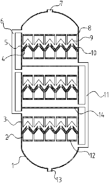
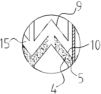
[0036] A new high-efficiency methanol synthesis tower, comprising a tower body 1, the top of the tower body 1 is provided with a gas supply nozzle 7, and the bottom is provided with a methanol outlet 13, and the tower body 1 is divided into several reaction chambers by partitions 14; The reaction chamber is communicated with the gas distribution pipe 6 and the liquid collecting pipe 11; the reaction chamber is provided with a combined tray; the combined tray includes a first tray 10 and a second tray 4; the first tray Tray 10 is positioned at the top of second tray 4; Described first tray 10 and second tray 4 are all provided with several conical cavities; The bottom opening of described conical cavity, and place tray The lower space of the first tray 10 is connected with the conical cavity on the first tray 10 and the conical cavity on the second tray 4 has the same shape size, quantity and open position; the first tray 10 and the second tray 4 The two trays 4 cooperate with ...

Embodiment 2

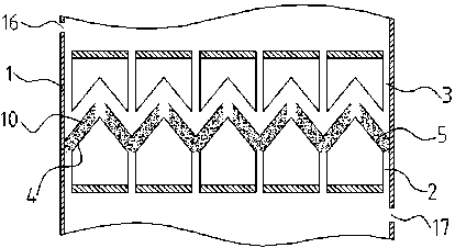
[0039] The difference between embodiment 2 and embodiment 1 is that the upper tube plate 8 is located above the first tray 10, and several inlet pipes 3 are vertically arranged between the upper tube plate 8 and the first tray 10; The upper end of the air inlet pipe 3 runs through the upper tube sheet 8 , and the lower end communicates with the second air inlet 19 on the first tray 10 . The arrangement of the upper tube sheet 8 can protect the first tray 10 to a certain extent, preventing the high-pressure low-temperature mixed gas from being directly sprayed onto the first tray 10 below the gas supply nozzle, causing damage to the first tray 10 . The upper tube sheet 8 is fixedly connected to the inner wall of the tower body. The low-temperature synthesis gas enters the tower from the gas supply nozzle 7 at the top of the methanol synthesis tower, passes through the upper tube plate 8, and is directly transported to the reaction layer by the inlet pipe 3 for reaction. The up...


PUM


Abstract

A novel efficient methanol synthesis tower comprises a tower body, wherein a gas supply nozzle is arranged at the top of the tower body, a methanol outlet is formed in the bottom, and the tower body is divided into multiple reaction cavities by partition boards; the reaction cavities are communicated through gas distributing pipes and liquid collecting pipes; a combined tower tray is arranged in each reaction cavity; each combined tower tray comprises a first tower tray and a second tower tray; each first tower tray is located above the corresponding second tower tray; a plurality of conical cavities are formed in each of the first tower trays and the second tower trays; the bottoms of the conical cavities are open and communicated with lower space of the tower trays; the conical cavitiesin the first tower trays and the conical cavities in the second tower trays have the same shape, size and number and are formed in the same positions; each first tower tray and the corresponding second tower tray are mutually matched to form a reaction layer; the reaction layers are filled with particle catalysts; second gas inlets are formed in the tops of the conical cavities in the first towertrays; liquid outlets are formed in edges of bottom openings of the conical cavities in the second tower trays.

Description

technical field [0001] The invention relates to a methanol synthesis device, in particular to a novel high-efficiency methanol synthesis tower. Background technique [0002] Methanol is a colorless, alcoholic and volatile liquid with a wide range of uses. It is the basic organic chemical raw material and high-quality fuel. It is mainly used in the fields of fine chemical industry and plastics, and is used to manufacture various organic products such as formaldehyde, acetic acid, and methylammonium, and is also one of the important raw materials for pesticides and medicines. Almost all methanol is synthesized industrially by pressurized catalytic hydrogenation of carbon monoxide. In the prior art, methanol is usually produced by passing a mixture of carbon monoxide and hydrogen into a reaction tube bundle provided with a granular catalyst. In this way, as the mixed gas flows downward in the tube bundle, it contacts and reacts with the catalyst to generate methanol and side ...

Claims


Application Information

Patent Timeline
IPC IPC(8): B01J8/02B01J8/04C07C31/04C07C29/152
CPCB01J8/02B01J8/0278B01J8/0292B01J8/04C07C29/152C07C31/04Y02P20/52
Inventor 王青春赖杰懿汪益均吴川
Owner SICHUAN BLUSR MACHINERY
Why Eureka
Try Eureka