Lifting device for ocean platform and ocean platform

A technology for offshore platforms and lifting devices, applied in the field of lifting devices and offshore platforms, can solve the problems that the pins are not easy to connect with the holes, and the position accuracy is difficult to guarantee.

Pending Publication Date: 2021-05-18
SICHUAN HONGHUA PETROLEUM EQUIP
View PDF0 Cites 0 Cited by
  • Summary
  • Abstract
  • Description
  • Claims
  • Application Information

AI Technical Summary

Problems solved by technology

[0003] The object of the present invention is to provide a lifting device for an offshore platform and an offshore platform for the problem that the pin is not easily connected to the hole due to the difficulty in ensuring the position accuracy of the upper hole of the leg of the offshore platform in the prior art.

Method used


Image

  • Lifting device for ocean platform and ocean platform
  • Lifting device for ocean platform and ocean platform
  • Lifting device for ocean platform and ocean platform

Examples


Embodiment 1

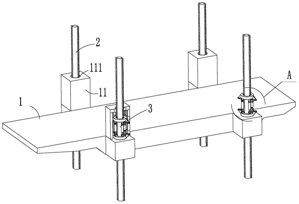
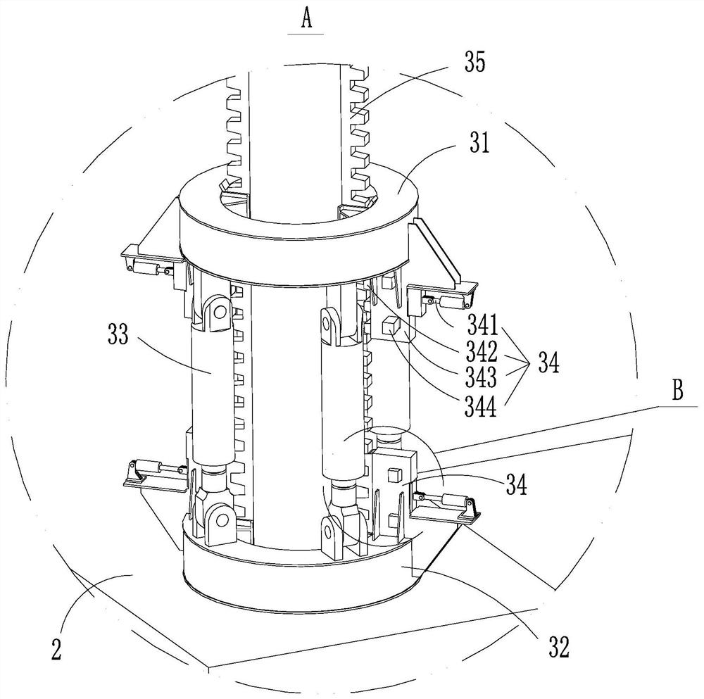
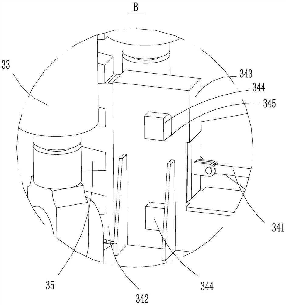
[0037] see Figure 1-Figure 4 , the embodiment of the present invention provides a lifting device 3 for an offshore platform 1 , which includes a first beam 31 , a second beam 32 , a lifting drive 33 , a clamping device 34 and a clamping rack 35 .

[0038] The first beam body 31 is connected to the second beam body 32 through the lifting driver 33, and the length of the lifting driver 33 can be extended or shortened, so that the distance between the first beam body 31 and the second beam body 32 can be increased or decreased. Small. The first beam body 31 is configured as a ring structure, and the first beam body 31 is sheathed on the leg 2 . The second beam body 32 is configured as a ring structure, and the second beam body 32 is sleeved on the leg 2 and fixedly connected to the platform. The number of lifting driving parts 33 is set to be multiple, and the multiple lifting driving parts 33 are evenly distributed in the circumferential direction of the first beam body 31 . ...

Embodiment 2

[0059] see figure 1 , the embodiment of the present invention provides an ocean platform, which includes a platform 1 , legs 2 and the lifting device 3 provided in Embodiment 1. The number of legs 2 is at least three. In this embodiment, four legs 2 are provided, and each leg 2 is connected to a lifting device 3 .

[0060] The second beam body 32 of the lifting device 3 is connected to the platform 1 , and the first beam body 31 and the second beam body 32 are sheathed on the leg 2 . The clamping rack 35 is arranged on the pile leg 2 and is fixedly connected with the pile leg 2 . Specifically, the clamping rack 35 is connected to the leg 2 by welding.

[0061] An installation box 11 is provided on the platform 1. The installation box 11 is provided with a through hole 111 for the legs 2 to pass through. An installation cavity is formed on the installation box 11, and the lifting device 3 is placed in the installation cavity. When the lifting driving part 33 is in the retrac...


PUM


Abstract

The invention relates to the field of engineering equipment such as ocean wind power installation vessels and ocean oil drilling platforms, in particular to a lifting device for an ocean platform and the ocean platform. The lifting device comprises a first beam body, a second beam body, a lifting driving part, a clamping rack and two clamping devices, wherein the second beam body is fixedly connected with the ocean platform; the first beam body and the second beam body are connected through the lifting driving part; the clamping rack is fixedly connected with pile legs; and one of the two clamping devices is connected with the first beam body, the other clamping device is connected with the second beam body, the clamping device comprises a clamping block matched with the clamping rack, and the clamping block and the clamping rack can be clamped or separated. The ocean platform comprises the lifting device for the ocean platform. The clamping rack of the lifting device for the ocean platform is easily aligned and matched with the clamping device, a hydraulic station and a hydraulic cylinder can be prevented from being in a working state for a long time, and safety is improved. A good using effect is achieved in the environment that the seabed surface is uneven.

Description

technical field [0001] The invention relates to the field of engineering equipment such as offshore wind power installation ships and offshore oil drilling platforms, in particular to a lifting device for the offshore platform and the offshore platform. Background technique [0002] The offshore platform often needs to be equipped with a lifting device to realize the lifting of the offshore platform. In the prior art, the structure of the lifting device for the offshore platform is usually set as follows: according to the actual production, the pin hole is bored at the preset position on the leg, and the platform is equipped with an oil cylinder and a bolt, and the bolt is used to connect with the leg on the leg. The pins and holes are connected, and the platform is raised and lowered relative to the legs through multiple oil cylinders. In actual use, because the position accuracy of the pin hole is difficult to guarantee, the plug is not easy to align with the pin hole. I...

Claims


Application Information

Patent Timeline
Patent Type & Authority Applications(China)
IPC IPC(8): E02B17/00E02B17/08
CPCE02B17/00E02B17/08E02B17/0809E02B17/0818
Inventor 张泽
Owner SICHUAN HONGHUA PETROLEUM EQUIP
Why Eureka
Try Eureka