Center-adjustable ball spherical hinge joint and center adjusting method of center-adjustable ball spherical hinge joint

A technology of ball joints and hinge joints, which is applied in the direction of rotating parts, bearings, and bearing components that resist centrifugal force, and can solve the problem that ball joints cannot meet the motion accuracy requirements of high-precision occasions, the motion accuracy decreases, and the gap between the ball head and the ball socket increases. Large and other problems, to achieve the effect of mature processing technology, reduce eccentricity error, and improve centering accuracy

Active Publication Date: 2016-10-12
HANGZHOU DIANZI UNIV
View PDF5 Cites 10 Cited by
  • Summary
  • Abstract
  • Description
  • Claims
  • Application Information

AI Technical Summary

Problems solved by technology

Due to processing and assembly errors, the ball joint is usually in an eccentric state. At the same time, under the long-term movement of the ball joint, the wear of the ball head and the ball socket will cause the gap between the ball head and the ball socket to increase, and the motion accuracy will decrease. The hinge joint cannot meet the motion accuracy requirements of high-precision occasions

Method used


Image

  • Center-adjustable ball spherical hinge joint and center adjusting method of center-adjustable ball spherical hinge joint
  • Center-adjustable ball spherical hinge joint and center adjusting method of center-adjustable ball spherical hinge joint
  • Center-adjustable ball spherical hinge joint and center adjusting method of center-adjustable ball spherical hinge joint

Examples


Embodiment Construction

[0030] The present invention will be further described below in conjunction with the accompanying drawings.

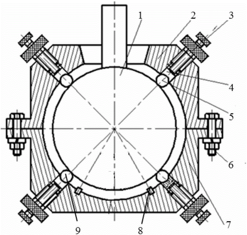
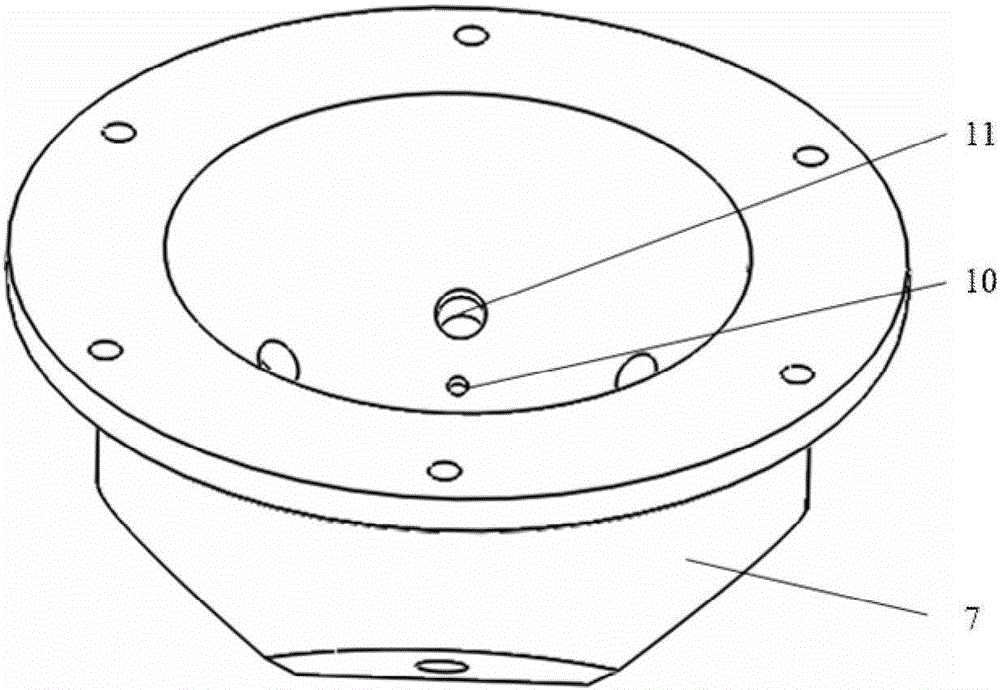
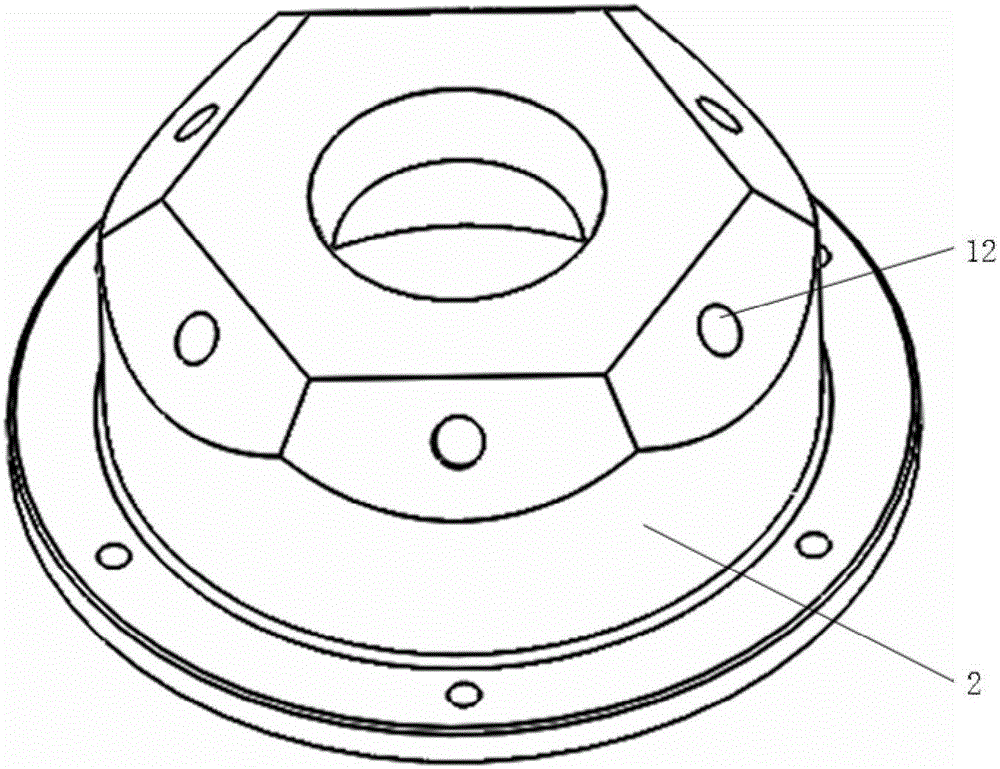
[0031] like figure 1 , 2 , 3 and 4, an adjustable ball joint, including ball head 1, constrained ball socket 2, double-threaded centering mechanism 3, cylindrical block 4, constrained ball steel ball 5, supporting ball socket 7, Support ball steel ball 9 and displacement detection system 8. The support ball socket 7 is used as the base of the present embodiment; the support ball socket 7 is provided with six support ball guide holes 11 evenly distributed along the circumference, and the double-threaded centering mechanism 3, the cylindrical block 4 and the support ball guide hole 11 are installed in the support ball socket 7. Ball steel ball 9; the tail plane end of the cylindrical block 4 in the ball guide hole is in contact with the double-threaded centering mechanism 3, and the arc surface of the head is in contact with the support ball steel ball 9; the six displ...


PUM


Abstract

The invention discloses a center-adjustable ball spherical hinge joint and a center adjusting method of the center-adjustable ball spherical hinge joint. Due to machining and assembling errors, a spherical hinge joint is in an eccentric state usually. Supporting ball guide holes are formed in a supporting ball socket of the ball spherical hinge joint. A displacement sensor is installed in a sensor installation hole of the supporting ball socket. Restraining ball guide holes are formed in a restraining ball socket. Double-thread center adjusting mechanisms are installed in the supporting ball guide holes and the restraining ball guide holes to adjust ball steel balls. The center adjusting method includes the steps that the center-adjustable ball spherical hinge joint is installed; when the double-thread center adjusting mechanisms are installed, main threaded columns and auxiliary threaded columns rotate in the opposite directions, and the restraining ball steel balls and the supporting ball steel balls are quickly located; and when centering adjustment is conducted by the double-thread center adjusting mechanisms, the main threaded columns and the auxiliary threaded columns rotate in the same direction. The double-thread structures rotate in the opposite directions when the eccentric error is relatively large, and the eccentric error is quickly reduced; and the double-thread structures rotate in the same direction when the eccentric error is relatively small, and the centering condition of the balls and the ball sockets are finely adjusted.

Description

technical field [0001] The invention belongs to the field of ball and ball joints, and in particular relates to an adjustable centering ball and ball joint and a centering method thereof. Background technique [0002] The ball joint is a three-degree-of-freedom mechanical joint with compact structure and flexible movement. It is gradually being widely used in many fields such as robots, parallel mechanisms, automobiles, and motors. [0003] The rolling ball joint adopts the distribution of ball steel balls between the ball head and the ball socket, and the sliding contact between the ball head and the ball socket is converted into the rolling contact between the ball head and the ball steel ball and the ball socket and the ball steel ball, thereby Reduce the friction between the ball head and the ball socket, but because the rolling contact position between the ball head and the ball steel ball is a contact point, the contact stress is concentrated, resulting in a large Hert...

Claims


Application Information

Patent Timeline
Patent Type & Authority Applications(China)
IPC IPC(8): F16C11/06
CPCF16C11/06F16C2231/00F16C2237/00
Inventor 王文唐超锋朱晔文时光卢科青赵鼎成裘荣波
Owner HANGZHOU DIANZI UNIV
Why Eureka
Try Eureka