
Locking clamping piece for zipper type wall part

A technology for walls and parts, applied in the field of zipper-type wall parts locking clips, can solve problems such as inability to adapt to construction requirements

Pending Publication Date: 2021-05-18
内蒙古拉锁式新型建材科技有限公司
View PDF0 Cites 0 Cited by
  • Summary
  • Abstract
  • Description
  • Claims
  • Application Information

AI Technical Summary

Problems solved by technology

This point runs counter to the development and construction technology of prefabricated buildings. The original standards and construction operating procedures formulated for the wet construction method of "zipper" wall panels and wall component blocks cannot be used in the construction of prefabricated buildings. Adapt to new construction requirements

Method used


Image

  • Locking clamping piece for zipper type wall part
  • Locking clamping piece for zipper type wall part
  • Locking clamping piece for zipper type wall part

Examples


specific Embodiment 1

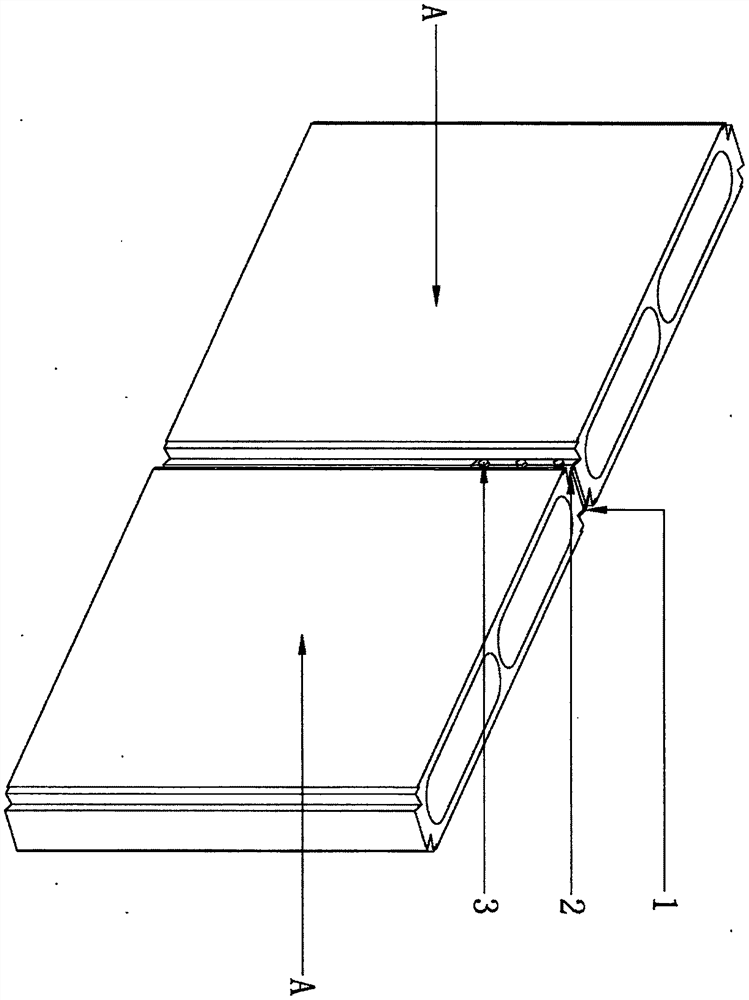
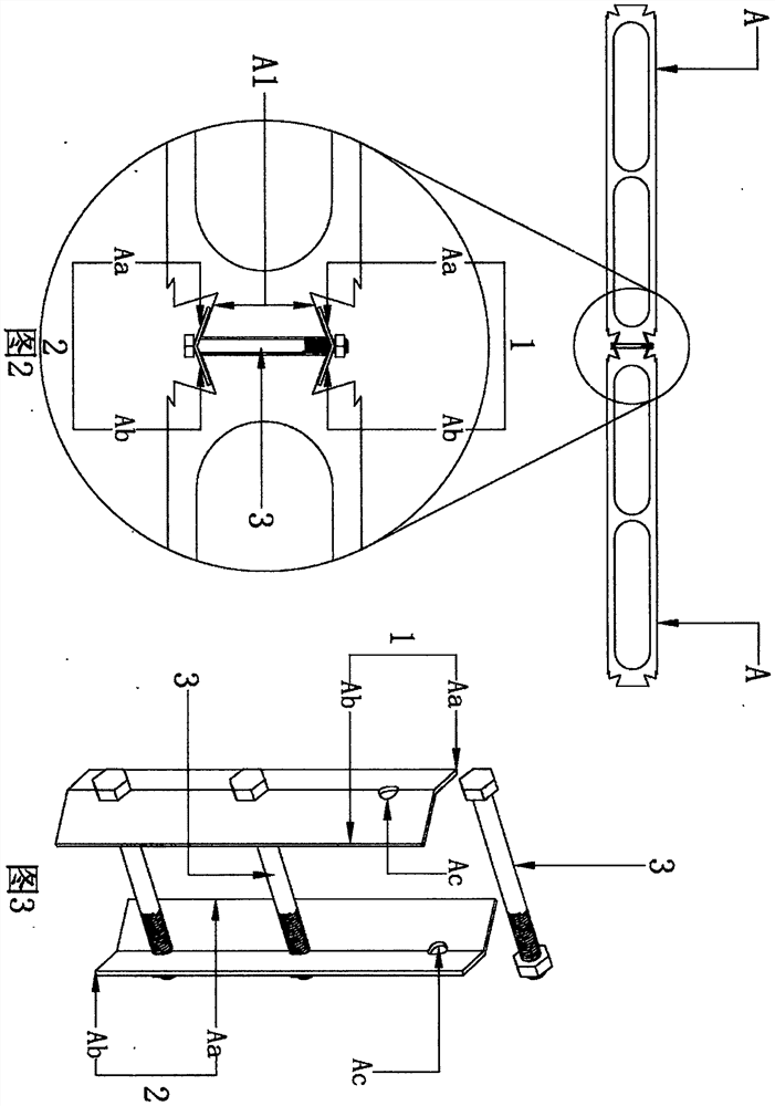
[0070] Such as figure 2 image 3 As shown, the locking clip includes a splint assembly I 1 , a splint assembly II 2 and a bolt assembly 3 . The splint assembly I 1 and the splint assembly II 2 are connected by a bolt assembly 3 . Both the splint assembly I 1 and the splint assembly II 2 include a left wing plate Aa and a right wing plate Ab fixedly connected together. The shapes of the side A1 match, and the left wing plate Aa and the right wing plate Ab form a V shape with an angle less than 180 degrees and greater than 90 degrees after being connected. The splint assembly I 1 and the splint assembly II 2 are clamped on the trapezoidal edge A1 of the zipper convex groove of the zipper type wall part A through its left wing plate Aa and right wing plate Ab to complete the lock between two lock type wall parts A. connect.

specific Embodiment 2

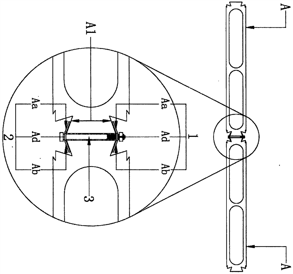
[0072] A locking clip for a zipper type wall part based on the first embodiment above. Such as Figure 4 Figure 5 As shown, the splint assembly I 1 and the splint assembly II 2 also include a straight connecting plate Ad; the left wing Aa and the right wing Ab are fixedly connected to both ends of the straight connecting plate Ad.

specific Embodiment 3

[0074] Such as Image 6 Figure 7 As shown, the locking clip includes a splint assembly I 1 , a splint assembly II 2 and a bolt assembly 3 , and the splint assembly I 1 and splint assembly II 2 are connected through the bolt assembly 3 . Both the splint assembly I 1 and the splint assembly II 2 include a left wing plate Aa and a right wing plate Ab fixedly connected together, the left wing plate Aa and the right wing plate Ab are straight shapes with an angle of 180 degrees after connection, and the left wing plate A protruding tenon strip Ae is formed on the lateral ends of the plate surface of the plate Aa and the right wing plate Ab. The splint assembly I 1 and the splint assembly II 2 are clipped on the trapezoidal edge A1 of the zipper convex groove of the zipper type wall part A through the two ends of the left wing plate Aa and the right wing plate Ab. Block lock type connection between wall parts A.

[0075] specific figure 2 Figure 4 The connection setting angl...


PUM


Abstract

The invention provides a locking clamping piece for a zipper type wall part. The locking clamping piece can be applied to connection, locking and fastening between zipper type wall boards or wall part building blocks or connection, locking and fastening between the zipper type wall boards or the wall part building blocks and beams and the ground. The locking clamping piece comprises a clamping plate assembly I, a clamping plate assembly II and a bolt assembly. The clamping plate assembly I and the clamping plate assembly II are connected through the bolt assembly. The clamping plate assembly I and the clamping plate assembly II each comprises a left wing plate and a right wing plate which are fixedly connected together, the plate body shapes of the left wing plates and the right wing plates are matched with the shape of the trapezoid edge of a zipper convex groove of the zipper type wall part, and the left wing plates and the right wing plates are in a V shape with the angle smaller than 180 degrees and larger than 90 degrees after being connected. The clamping plate assembly I and the clamping plate assembly II are clamped and buckled on the trapezoid edges of the zipper convex grooves of the zipper type wall parts through the left wing plates and the right wing plates of the clamping plate assembly I and the clamping plate assembly II so as to complete connection between the two zipper type wall parts.

Description

[0001] 1. Technical field [0002] A locking clip for zipper type wall parts, relates to a combination clip for installing building parts, in particular to a zipper type wall part locking clip applied to prefabricated buildings. [0003] 2. Background technology [0004] Building wall panels and wall block components have been used in the fields of building frame structures and steel structures for nearly a hundred years. In the past, in the application of building wall boards and wall block components in the above structures, cement paste or other adhesive pastes were used to bond between wall boards and wall blocks. Due to the difference in the wet expansion and drying shrinkage values ​​of the wall boards, wall blocks and adhesive paste, cracking often occurs between the wall boards and wall blocks. With the emergence of "zipper type" wall panels and wall component blocks, the cracking phenomenon that often occurs between wet expansion and dry shrinkage wall panels and wall...

Claims


Application Information

Patent Timeline
IPC IPC(8): E04B2/00E04B2/74E04B2/82
CPCE04B2/00E04B2/74E04B2/82
Inventor 姚井祥李雪杰修建姚兰
Owner 内蒙古拉锁式新型建材科技有限公司
Learn More