Flue gas detection method based on FTIR technology

A technology for smoke detection and technology, which is used in measurement devices, color/spectral property measurement, suspension and porous material analysis, etc., and can solve problems such as interference, inaccurate detection results, and inevitable simultaneous removal.

Pending Publication Date: 2021-05-18
HANGZHOU PUYU TECH DEV CO LTD
View PDF7 Cites 0 Cited by
  • Summary
  • Abstract
  • Description
  • Claims
  • Application Information

AI Technical Summary

Problems solved by technology

At present, most analysis devices use the method of reducing the moisture in the flue gas for monitoring. The methods adopted include the cooling dehumidification method, the nano-pipe water removal method, etc., but these methods inevitably remove the components to be measured in the flue gas at the same time during the water removal process. Remove a part, resulting in inaccurate test results
[0004] 2. H in flue gas 2 O high content components will seriously interfere with low content gas components in the flue gas, how to eliminate H 2 The impact of O on the detection results is a difficult point in the analysis process
[0005] The PE plant company proposed a VAC method for moisture correction, which is used for detection and analysis in the atmospheric environment. This method cannot be fully applied to the working conditions of high-temperature flue gas
[0006] 3. Under the basic national policy of winning the blue sky defense war, more and more pollutant components need to be monitored in the flue gas. Most of the devices used before are one device to monitor one factor, which cannot cover all the components to be monitored in the flue gas. all factors
[0007] 4. In the supervision of flue gas emission, the supervision unit usually needs on-site sampling for flue gas laboratory analysis. In this process, due to the superimposition of various error factors, the monitoring results are often not very accurate. Therefore, the supervision department needs a portable on-site monitoring FT device for smoke detection

Method used


Image

  • Flue gas detection method based on FTIR technology
  • Flue gas detection method based on FTIR technology
  • Flue gas detection method based on FTIR technology

Examples


Embodiment 1

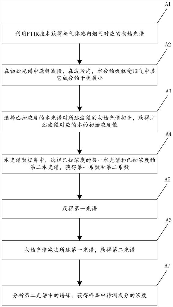
[0031] figure 1 The flow chart of the smoke detection method based on FTIR technology of the embodiment of the present invention is given, as figure 1 Shown, described smoke detection method based on FTIR technology comprises the following steps:

[0032] (A1) Using FTIR technology to obtain an initial spectrum corresponding to the flue gas in the gas pool, the flue gas contains moisture;

[0033] The flue gas is heated to 180 degrees in the pipeline from the flue to the gas pool to prevent the moisture in the flue gas from condensing and losing the components to be measured;

[0034] (A2) Select a band in the initial spectrum, within the band, the absorption of moisture is least interfered by other components in the flue gas, such as not interfered by other components;

[0035] (A3) Select the water spectrum of known concentration to fit the initial spectrum of the band, and obtain the initial concentration value C of the water corresponding to the band 0 ;

[0036] (A4) ...

Embodiment 2

[0047] An application example of the smoke detection method based on FTIR technology according to Embodiment 1 of the present invention.

[0048] In this application example, the smoke detection method based on FTIR technology in the embodiment of the present invention includes the following steps:

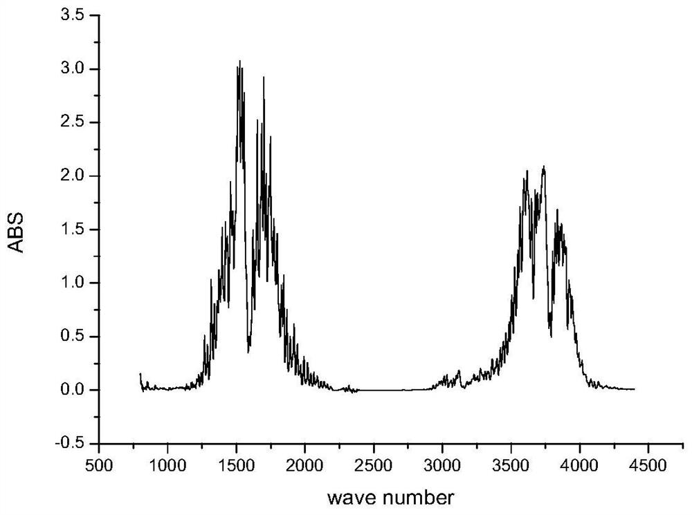
[0049] (A1) Use FTIR technology to obtain the initial spectrum corresponding to the flue gas in the gas pool, such as figure 2 As shown, the flue gas contains moisture;

[0050] The flue gas is heated to 180 degrees in the pipeline from the flue to the gas pool to prevent the moisture in the flue gas from condensing and losing the components to be measured;

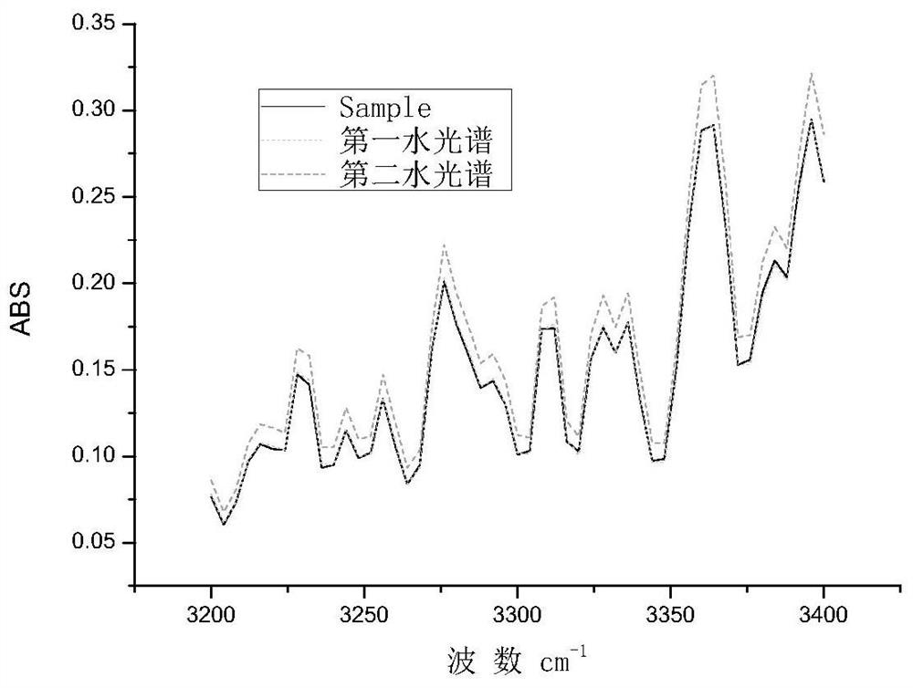
[0051](A2) Select a waveband in the initial spectrum, the waveband is 3200-3400 wavenumber, and in the waveband, the absorption of moisture is minimally interfered by other components in the flue gas, such as not interfered by other components;

[0052] (A3) Select the water spectrum of known concentration to fit the initi...


PUM


Abstract

The invention provides a flue gas detection method based on an FTIR technology. The flue gas detection method based on the FTIR technology comprises the following steps that: (A1) an initial spectrum containing water is obtained by utilizing the FTIR technology; (A2) a water absorption wave band which is not interfered by other components is selected from the initial spectrum; (A3) a water spectrum with known concentration is selected to fit the initial spectrum of the wave band, so that an initial concentration value C0 of water corresponding to the wave band is obtained; (A4) in a water spectrum database, a first water spectrum S1 with a known concentration C1 and a second water spectrum S2 with a known concentration C2 are selected, the concentration C1 is smaller than C0, the absolute value of the difference of C1 and C0 is minimum, the concentration C2 is larger than C0, and the absolute value of the difference of C2 and C0 is minimum; the initial spectrum of a first wave is fitted by using a first water spectrum with the known concentration C1 and the second water spectrum with the known concentration C2, so that a coefficient X1 corresponding to the first water spectrum and a coefficient X2 corresponding to the second water spectrum can be obtained; (A5) a first spectrum is obtained according to an equation that S3=X1*S1+X2*S2; (A6) the first spectrum is subtracted from the initial spectrum, so that a second spectrum is obtained; and (A7) the spectrum peak in the second spectrum is analyzed, so that the concentration of a component to be detected in the sample is obtained. The method has the advantages of accurate detection and the like.

Description

technical field [0001] The invention relates to gas detection, in particular to a smoke detection method based on FTIR technology. Background technique [0002] At present, there are many problems in the use of portable FTIR flue gas analyzers: [0003] 1. The current flue gas temperature is relatively high, especially the flue gas temperature of waste incineration plants reaches above 150 degrees, and the moisture concentration is as high as 30%. At present, most analysis devices use the method of reducing the moisture in the flue gas for monitoring. The methods adopted include the cooling dehumidification method, the nano-pipe water removal method, etc., but these methods inevitably remove the components to be measured in the flue gas at the same time during the water removal process. Remove a part, resulting in inaccurate test results. [0004] 2. H in flue gas 2 O high content components will seriously interfere with low content gas components in the flue gas, how to ...

Claims


Application Information

Patent Timeline
Patent Type & Authority Applications(China)
IPC IPC(8): G01N15/06G01N21/31
CPCG01N15/06G01N21/31G01N2015/0693
Inventor 周新奇刘立鹏李天麟刘妍王越峰郭中原
Owner HANGZHOU PUYU TECH DEV CO LTD
Why Eureka
Try Eureka