
Switching unit state detection method and application device

A switching unit and state detection technology, which is applied in the direction of measuring devices, circuit devices, battery circuit devices, etc., can solve problems such as unusable, increased hardware costs, and increased number of anti-reverse diodes

Pending Publication Date: 2021-05-18
SUNGROW POWER SUPPLY CO LTD
View PDF10 Cites 1 Cited by
  • Summary
  • Abstract
  • Description
  • Claims
  • Application Information

AI Technical Summary

Problems solved by technology

like figure 1 As shown, the currently commonly used switching unit state detection method requires an external battery during the detection process, and uses the voltage difference generated by the battery voltage at both ends of the switching unit to determine whether the switching unit is stuck. However, in order to protect the charging pile. Power factor correction circuit PFC, resonant circuit LLC and other charging circuits need to add an additional anti-reverse diode on the output side of the charging pile, which will make the existing switching unit state detection method unusable, and if the anti-reverse diode is placed on the front end of the switching unit , when multiple LLCs are connected in parallel, the number of anti-reverse diodes will be increased, thereby increasing the hardware cost

Method used


Image

  • Switching unit state detection method and application device
  • Switching unit state detection method and application device
  • Switching unit state detection method and application device

Examples


Embodiment Construction

[0089] The following will clearly and completely describe the technical solutions in the embodiments of the application with reference to the drawings in the embodiments of the application. Apparently, the described embodiments are only some of the embodiments of the application, not all of them. Based on the embodiments in this application, all other embodiments obtained by persons of ordinary skill in the art without creative efforts fall within the protection scope of this application.

[0090] In order to facilitate the description of the switching unit state detection method provided by various embodiments of the present invention, firstly, the related concepts involved in the present invention are explained:

[0091] Preset Port Voltage: Combined figure 1 As shown, the preset port voltage of LLC refers to the voltage provided by the output terminal of LLC between the LLC circuit and the switching unit. The preset port voltage is the theoretical voltage output to the down...


PUM


Abstract

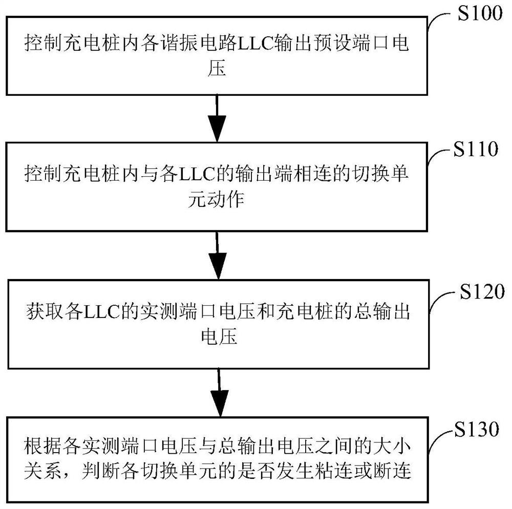
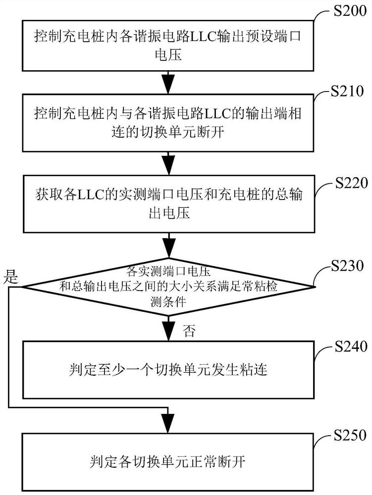
The switching unit state detection method and the application device provided by the invention are applied to the technical field of direct current charging, and the method comprises the following steps: after controlling each resonant circuit LLC in a charging pile to output a preset port voltage, controlling a switching unit connected with the output end of each LLC in the charging pile to act; and then obtaining actual measurement port voltage of each LLC and total output voltage of the charging pile, and judging whether each switching unit is adhered or disconnected according to the magnitude relationship between each actual measurement port voltage and the total output voltage. According to the invention, the preset port voltage output by the charging pile is taken as an implementation basis, whether each switching unit is adhered or disconnected can be detected based on the magnitude relationship between the actually measured port voltage of each LLC and the total output voltage of the charging pile, and then the switching unit does not depend on an external storage battery any more, so that the problems in the prior art are solved.

Description

technical field [0001] The invention relates to the technical field of DC charging, in particular to a method for detecting the state of a switching unit and an application device. Background technique [0002] see figure 1 , figure 1 It is a structural block diagram of a DC charging pile in the prior art. The charging pile is provided with a plurality of resonant circuits LLC, and a switching unit is connected between the output terminals of each LLC. figure 1 Shown by K1, K2 and K3, the output voltage of the charging pile can be adjusted by changing the connection state of each switching unit, so as to adapt to different charging requirements. [0003] Based on the above content, it can be seen that the working state of the switching unit in the charging pile plays a crucial role in whether the charging pile can work normally. Therefore, it is necessary to detect whether the switching unit in the charging pile is stuck. Such as figure 1 As shown, the currently commonly...

Claims


Application Information

Patent Timeline
IPC IPC(8): G01R31/00H02J7/00
CPCG01R31/00H02J7/0047Y02T10/7072Y02T90/12Y02T10/70
Inventor 张杰刘俊江冯林阳岳丰
Owner SUNGROW POWER SUPPLY CO LTD
Learn More