Test method of power electronic transformer

A technology of power electronics and testing methods, applied in the direction of measuring electrical variables, instruments, measuring electricity, etc., can solve the problems of no testing and certification standards, and the inability to accurately test and evaluate the performance and functions of power electronic transformers

Pending Publication Date: 2021-05-18
XUCHANG KETOP DETECTION TECH CO LTD
View PDF0 Cites 0 Cited by
  • Summary
  • Abstract
  • Description
  • Claims
  • Application Information

AI Technical Summary

Problems solved by technology

Power electronic transformers currently have no relevant testing and certification standards and syst...

Method used


Image

  • Test method of power electronic transformer
  • Test method of power electronic transformer
  • Test method of power electronic transformer

Examples


Embodiment 1

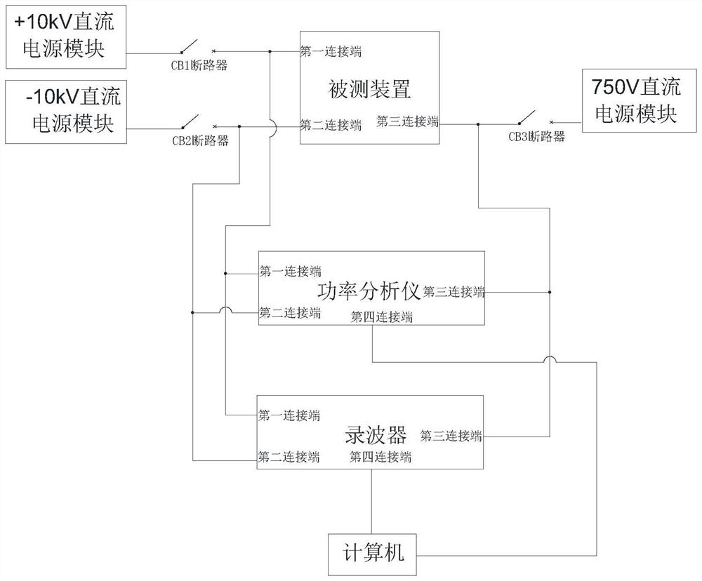
[0081] A test method for power electronic transformers, such as figure 1 shown, using a DC power electronic transformer test system. The tests include efficiency test, ripple test, power step response test, low voltage fault ride through test and high voltage fault ride through test.

[0082] The DC power electronic transformer testing system of the present invention is provided with a DC power module component, a power analyzer, a wave recorder, a circuit breaker component and a computer.

[0083] Among them, the circuit breaker assembly is used to control the disconnection and connection of the DC power module assembly and the device under test. DC power modules are used to provide power to the device under test. A power analyzer is used to collect power data from the device under test. The wave recorder is used to collect the ripple data of the device under test. The computer is used to obtain the test result according to the power data of the power analysis and the rip...

Embodiment 2

[0094] A test method for power electronic transformers, such as figure 2 , other features are the same as in Embodiment 1, and also have the following features:

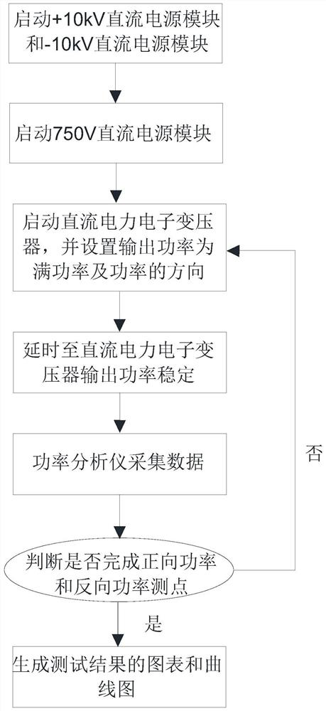
[0095] Efficiency tests include:

[0096] Step 1. Close the CB1 circuit breaker and the CB2 circuit breaker, and start the +10kV DC power module and the -10kV DC power module;

[0097] Step 2. Close the CB3 circuit breaker and start the 750V DC power module;

[0098] Step 3: Start the DC power electronic transformer, then set the output power to full power and set the direction of the power;

[0099] Step 4. Delay 1min to 5min until the output power of the DC power electronic transformer is stable;

[0100] Step 5: The power analyzer collects the power data of the time period A of the power electronic transformer, where A is a positive number;

[0101] Step 6: Determine whether the forward power and reverse power measurement points are completed, if not, go back to Step 3, if so, go to Step 7;

[0102] Step 7: ...

Embodiment 3

[0106] A test method for power electronic transformers, such as image 3 , other features are the same as in Embodiment 1, and also have the following features:

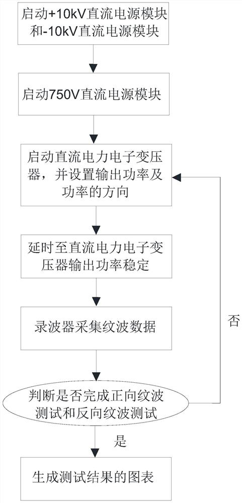
[0107] Ripple tests include:

[0108] Step 1. Close the CB1 circuit breaker and the CB2 circuit breaker, and start the +10kV DC power module and the -10kV DC power module;

[0109] Step 2. Close the CB3 circuit breaker and start the 750V DC power module;

[0110] Step 3. Start the DC power electronic transformer, and then set the output power and the direction of the power;

[0111] Step 4. Delay T 2 , until the output power of the DC power electronic transformer is stable;

[0112] Step 5. The wave recorder collects the ripple data of the power electronic transformer;

[0113] Step 6. Determine whether the forward ripple test and the reverse ripple test are completed, if not, go back to step 3, if so, go to step 7;

[0114] Step 7: The wave recorder transmits the collected ripple data to the computer, and the ...


PUM


Abstract

The invention discloses a test method of a power electronic transformer, which is carried out by adopting a direct-current power electronic transformer test system. The test comprises an effective rate test, a ripple test, a power step response test, a low-voltage fault ride-through test and a high-voltage fault ride-through test. The direct-current power electronic transformer test system is provided with a direct-current power supply module assembly, a power analyzer, an oscillograph, a circuit breaker assembly and a computer, wherein the circuit breaker assembly is used for controlling the disconnection and connection of the direct-current power supply module assembly and a tested device; the direct-current power supply module is used for providing power for the tested device; the power analyzer is used for collecting power data of the tested device; the oscillograph is used for collecting ripple data of the tested device; and the computer is used for obtaining a test result according to the power data of the power analysis and the ripple data of the oscillograph. The test method can test and evaluate the electrical performance and the protection function of the direct-current power electronic transformer, and can understand the performance of the direct-current power electronic transformer.

Description

technical field [0001] The invention relates to the field of power electronic technology detection, in particular to a test method of a power electronic transformer. Background technique [0002] Since the invention of the power transformer in the 19th century, it has become the basic component of the transmission and distribution system. Although the traditional power transformer has the advantages of simple manufacturing process and high reliability, it can only realize voltage level conversion and insulation isolation, and the function is relatively simple. It is impossible to isolate the distorted current and interference voltage on both sides of the transformer, which will affect the sensitive load on the one hand, and cause grid pollution on the other hand. Circulation, insulating oil pollutes the environment, etc. [0003] In the 1970s, the concept of power electronic transformer was proposed. Power electronic transformer (device under test) uses power electronic co...

Claims


Application Information

Patent Timeline
IPC IPC(8): G01R31/00G01R21/00
CPCG01R21/00G01R31/00
Inventor 陈卓贺春李宗原任高全曹元威李二海朱洋洋韩聪郭寅远
Owner XUCHANG KETOP DETECTION TECH CO LTD
Why Eureka
Try Eureka