Photographing lens assembly, image capturing unit and electronic device

A camera lens, lens technology, used in optical components, instruments, optics, etc.

Active Publication Date: 2021-05-18
LARGAN PRECISION
View PDF12 Cites 6 Cited by
  • Summary
  • Abstract
  • Description
  • Claims
  • Application Information

AI Technical Summary

Problems solved by technology

Because the optical lens in the past is not easy to achieve a balance between the requirements of imaging quality, sensitivity, aperture size, volume or viewing angle, so the present invention provides an optical lens to meet the needs

Method used


Image

  • Photographing lens assembly, image capturing unit and electronic device
  • Photographing lens assembly, image capturing unit and electronic device
  • Photographing lens assembly, image capturing unit and electronic device

Examples


no. 1 example

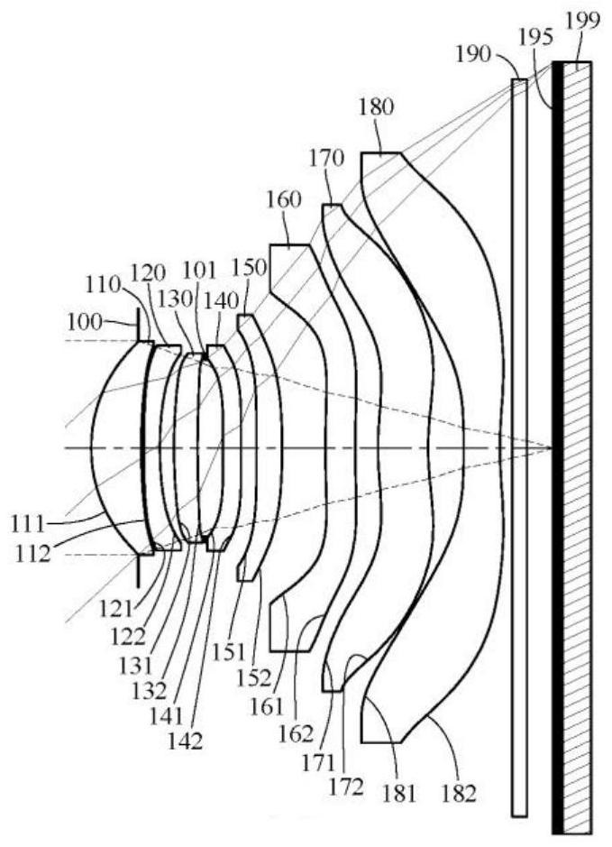
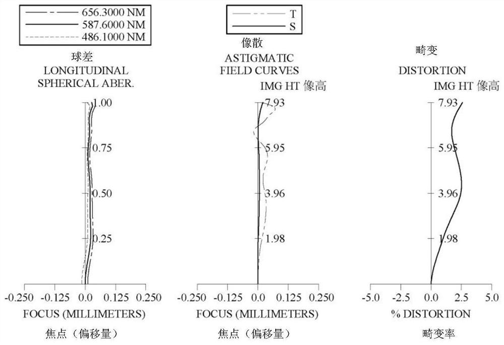
[0135] Please refer to Figure 1 to Figure 2 ,in figure 1 A schematic diagram of an imaging device according to a first embodiment of the present invention is shown, figure 2 From left to right are the spherical aberration, astigmatism and distortion curves of the first embodiment. Depend on figure 1 It can be seen that the image capturing device includes a camera lens group (not another number) and an electronic photosensitive element 199 . The camera lens group includes an aperture 100, a first lens 110, a second lens 120, a third lens 130, a diaphragm 101, a fourth lens 140, a fifth lens 150, a sixth lens 160, and a fifth lens 150 from the object side to the image side. The seventh lens 170 , the eighth lens 180 , an IR-cut filter element (IR-cut Filter) 190 and an imaging surface 195 . Wherein, the electronic photosensitive element 199 is disposed on the imaging surface 195 . The camera lens group includes eight lenses (110, 120, 130, 140, 150, 160, 170, 180), and th...

no. 2 example

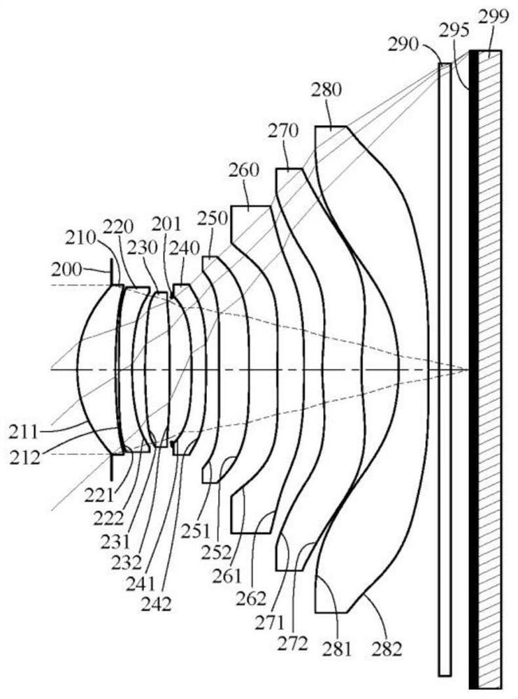
[0188] Please refer to Figure 3 to Figure 4 ,in image 3 A schematic diagram of an imaging device according to a second embodiment of the present invention is shown, Figure 4 From left to right are the spherical aberration, astigmatism and distortion curves of the second embodiment. Depend on image 3 It can be seen that the image capturing device includes a camera lens group (not another number) and an electronic photosensitive element 299 . The camera lens group includes an aperture 200, a first lens 210, a second lens 220, a third lens 230, a diaphragm 201, a fourth lens 240, a fifth lens 250, a sixth lens 260, and a fifth lens 250 from the object side to the image side. The seven lenses 270 , the eighth lens 280 , the infrared filter element 290 and the imaging surface 295 . Wherein, the electronic photosensitive element 299 is disposed on the imaging surface 295 . The camera lens group includes eight lenses (210, 220, 230, 240, 250, 260, 270, 280), and there is no ...

no. 3 example

[0206] Please refer to Figure 5 to Figure 6 ,in Figure 5 A schematic diagram of an imaging device according to a third embodiment of the present invention is shown, Image 6 From left to right are the spherical aberration, astigmatism and distortion curves of the third embodiment. Depend on Figure 5 It can be seen that the image capturing device includes a camera lens group (not another number) and an electronic photosensitive element 399 . The camera lens group includes an aperture 300, a first lens 310, a second lens 320, a diaphragm 301, a third lens 330, a diaphragm 302, a fourth lens 340, a fifth lens 350, and a sixth lens in sequence from the object side to the image side. The lens 360 , the seventh lens 370 , the aperture 303 , the eighth lens 380 , the infrared filter element 390 and the imaging surface 395 . Wherein, the electronic photosensitive element 399 is disposed on the imaging surface 395 . The camera lens group includes eight lenses (310, 320, 330, 34...


PUM


Abstract

The invention discloses a photographing lens assembly, including a total of eight lens elements which are, in order from an object side to an image side: a first lens element, a second lens element, a third lens element, a fourth lens element, a fifth lens element, a sixth lens element, a seventh lens element and an eighth lens element. The first lens element with positive refractive power has an object-side surface being convex in a paraxial region thereof. The second lens element has negative refractive power. The eighth lens element with negative refractive power has an object-side surface being concave in a paraxial region thereof. At least one lens element of the photographing lens assembly has at least one lens surface having at least one inflection point. When specific conditions are met, the photographing lens assembly can meet the requirements of miniaturization and high imaging quality at the same time. The invention further discloses an image capturing unit with the photographing lens assembly and an electronic device with the image capturing unit.

Description

technical field [0001] The invention relates to a camera lens group, an image pickup device and an electronic device, in particular to a camera lens group and an image pickup device suitable for the electronic device. Background technique [0002] With the improvement of semiconductor process technology, the performance of electronic photosensitive elements has been improved, and the pixel size can reach a smaller size. Therefore, optical lenses with high imaging quality have become an indispensable part. [0003] With the rapid development of science and technology, the application range of electronic devices equipped with optical lenses is wider, and the requirements for optical lenses are also more diverse. Since the conventional optical lens is not easy to achieve a balance among requirements such as imaging quality, sensitivity, aperture size, volume, or viewing angle, the present invention provides an optical lens to meet the requirements. Contents of the invention ...

Claims


Application Information

Patent Timeline
Patent Type & Authority Applications(China)
IPC IPC(8): G02B13/00G02B13/18
CPCG02B13/0045G02B9/64G02B13/0015
Inventor 薛钧哲陈泓硕王冠钧陈纬彧
Owner LARGAN PRECISION
Why Eureka
Try Eureka