RFID reader array antenna

An array antenna and reader technology, which is applied in the field of RFID reader array antenna, can solve the problems of narrow beam width of far-field antenna, misreading of far-field antenna label, large reading area of ​​metal frame covering shelf reading distance, etc.

Pending Publication Date: 2021-05-18
SUZHOU UNIV
View PDF0 Cites 0 Cited by
  • Summary
  • Abstract
  • Description
  • Claims
  • Application Information

AI Technical Summary

Problems solved by technology

However, tag misreading often occurs in far-field antennas due to their narrow beamwidths
[0004] For metal shelf applications, current near-field RFID antennas and far-f...

Method used


Image

  • RFID reader array antenna
  • RFID reader array antenna
  • RFID reader array antenna

Examples


Embodiment Construction

[0028] The above solution will be further described below in conjunction with specific embodiments. It should be understood that these examples are used to illustrate the present application and not limit the scope of the present application. The implementation conditions adopted in the examples can be further adjusted as the conditions of specific manufacturers, and the implementation conditions not indicated are usually the conditions in routine experiments.

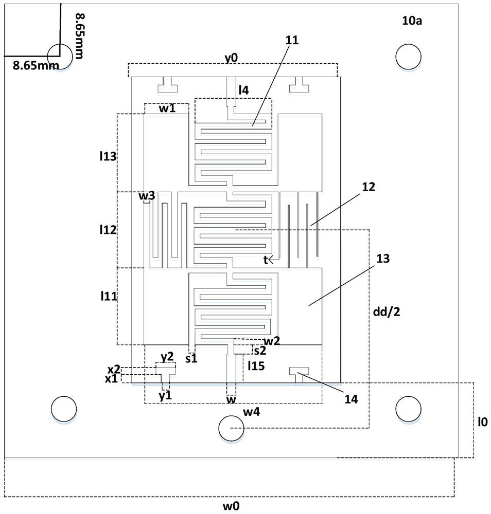
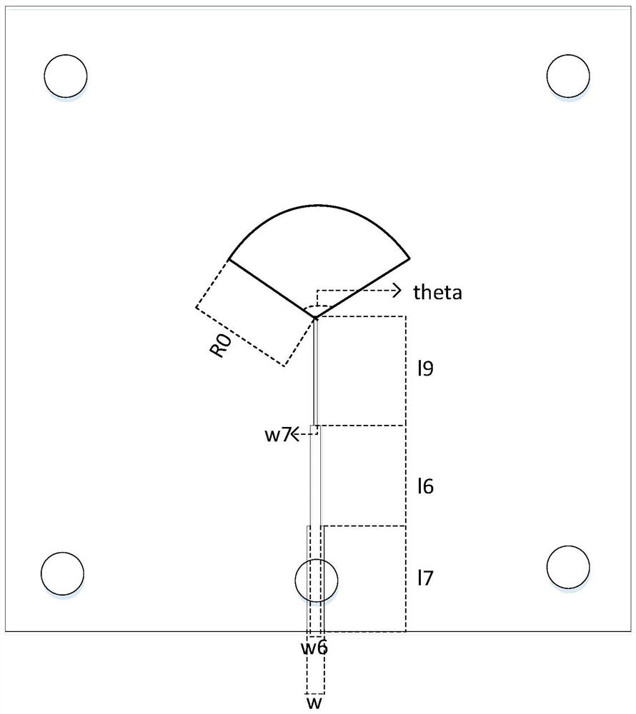
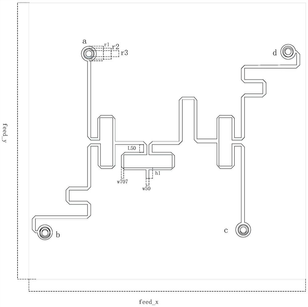
[0029] The present application provides an RFID reader array antenna, which includes three layers, which are an upper layer, a middle layer and a bottom layer from top to bottom. A reflector is placed on the bottom layer, a feeding network is placed on the middle layer, and multiple antenna units are placed on the upper layer, and the multiple antenna units are respectively connected to the feeding network, and the multiple antenna units and the feeding network share the reflector. Preferably, 4 antenna units are used...


PUM


Abstract

The invention provides an RFID reader array antenna. The RFID reader array antenna comprises a reflecting plate arranged on a bottom layer, a feed network arranged on a middle layer and a plurality of antenna units arranged on an upper layer, the plurality of antenna units are respectively connected with the feed network, and the plurality of antenna units and the feed network share the reflecting plate. According to the invention, an artificial transmission line structure is loaded on an antenna unit, and miniaturization is realized by changing the structures of a bent microstrip line and an interdigital microstrip line; through a power-dividing phase-shifting feed network, the antenna unit realizes the circular polarization characteristic. The antenna has the advantages of miniaturization, low profile, long identification distance and acceptable identification area.

Description

technical field [0001] The present application relates to the technical field of wireless communication, in particular to an RFID reader array antenna. Background technique [0002] RFID (Radio Frequency Identification) technology is a non-contact automatic identification technology. Its basic principle is to use the transmission characteristics and spatial coupling (inductive or electromagnetic coupling) of radio frequency signals to realize automatic identification of identified objects. In recent years, scholars at home and abroad have devoted themselves to the research of near-field RFID antennas. The challenge in designing a near-field reader antenna is to ensure that the magnetic field is uniform within the read area and rapidly decays outside the read area. Unlike far-field RFID antennas, near-field RFID reader antennas need to have low-gain characteristics to avoid misreading tags outside the read zone and to achieve a controlled read range. According to the coupl...

Claims


Application Information

Patent Timeline
IPC IPC(8): H01Q1/22H01Q1/36H01Q21/24H01Q21/00
CPCH01Q1/2225H01Q1/36H01Q21/0006H01Q21/24
Inventor 刘学观方艳茹
Owner SUZHOU UNIV
Why Eureka
Try Eureka