Aluminum alloy fixing and regular forming equipment
A technology for forming equipment and aluminum alloys, applied in metal processing equipment, positioning devices, storage devices, etc., can solve problems such as low production efficiency, uneven extrusion, and high labor intensity
- Summary
- Abstract
- Description
- Claims
- Application Information
AI Technical Summary
Problems solved by technology
Method used
Image
Examples
Embodiment 1
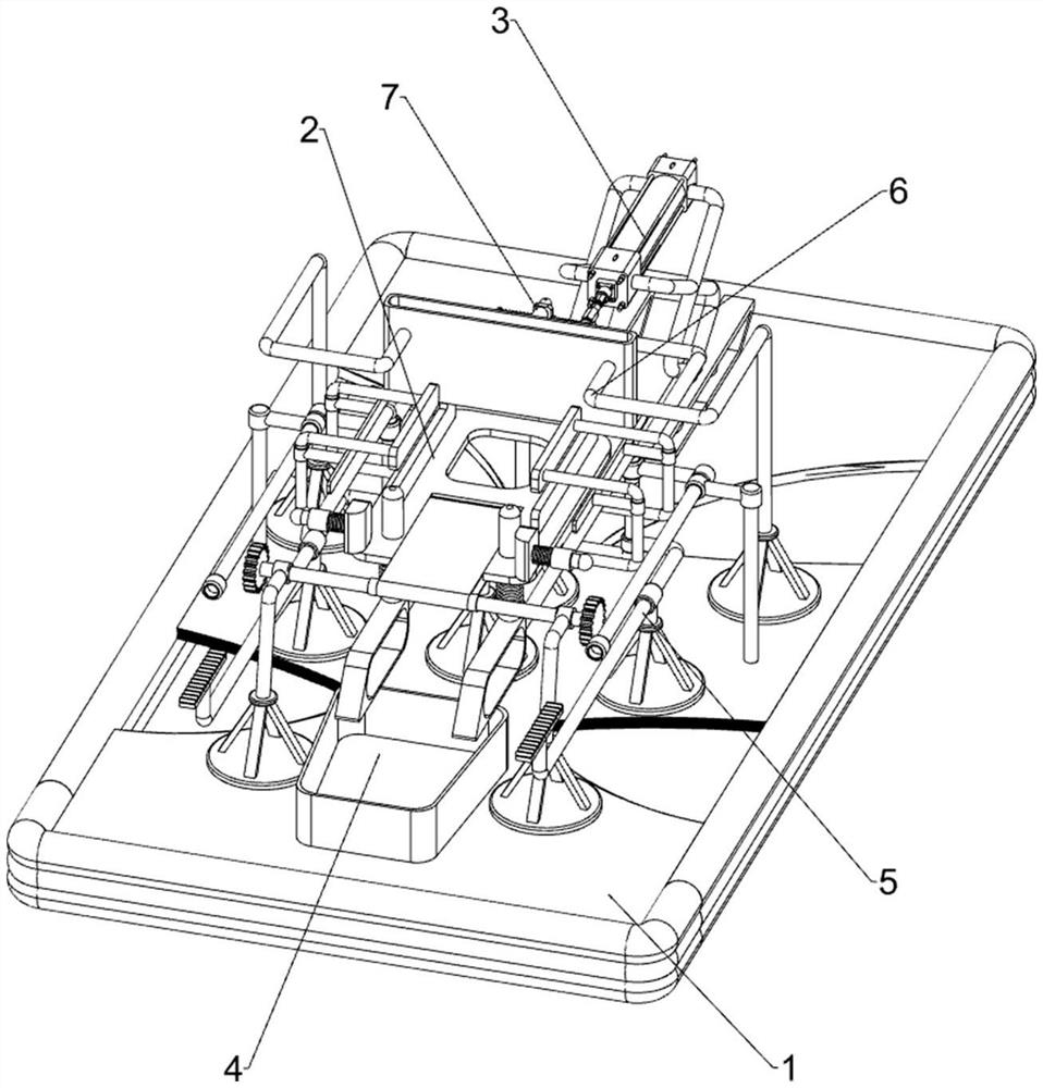
[0063] An aluminum alloy fixed rule forming equipment, such as figure 1 As shown, it includes a bottom plate 1, a positioning mechanism 2, an automatic bending mechanism 3 and a feeding mechanism 4. The upper middle part of the bottom plate 1 is provided with a positioning mechanism 2, and the bottom plate 1 is provided with an automatic bending mechanism 3. The automatic bending mechanism 3 is connected with the positioning mechanism. Mechanism 2 cooperates, and base plate 1 upper front part is provided with feeding mechanism 4, and feeding mechanism 4 is connected with positioning mechanism 2.
[0064] When people need to extrude the aluminum alloy pipe, first people put the aluminum alloy pipe in the positioning mechanism 2, and make the positioning mechanism 2 fix the aluminum alloy pipe, then make the automatic bending mechanism 3 run, and the automatic bending mechanism 3 The aluminum alloy pipe is bent, and then the positioning mechanism 2 is returned to its original po...
Embodiment 2
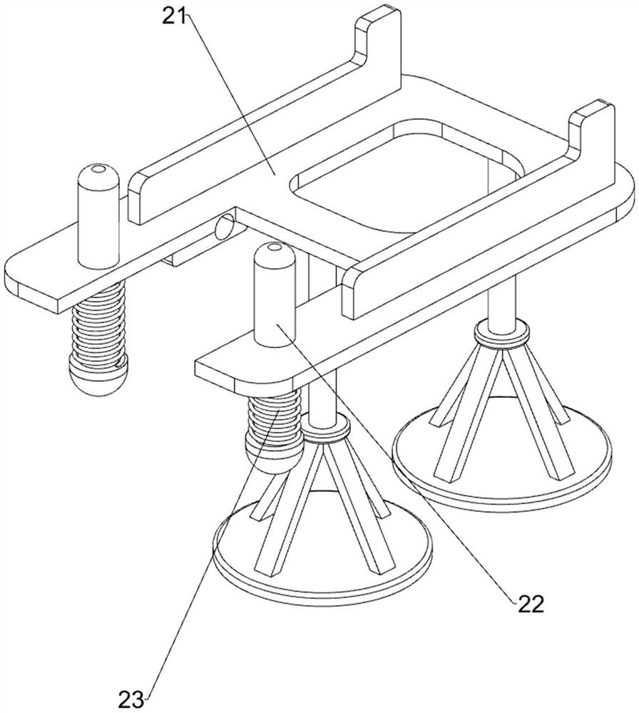
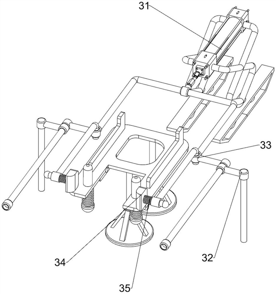
[0066] On the basis of Example 1, such as figure 2 , image 3 and Figure 4 As shown, the positioning mechanism 2 includes a working plate 21, a sliding positioning rod 22 and a first spring 23. The upper and middle part of the base plate 1 is provided with a working plate 21, and the left and right sides of the front part of the working plate 21 are all slidingly provided with a sliding positioning rod 22. First spring 23 is wound around the bottom of the sliding positioning rod 22 on the left and right sides, the top of the first spring 23 is connected with the working plate 21, and the bottom of the first spring 23 is connected with the sliding positioning rod 22.
[0067] People put the aluminum alloy tubing on the front part of the top side of the working board 21, then manually make the sliding positioning rod 22 slide upwards in the working board 21, the first spring 23 changes from the initial state to the compressed state, and the sliding positioning rod 22 makes th...
Embodiment 3
[0073] On the basis of Example 2, such as figure 1 , Figure 5 , Image 6 and Figure 7 As shown, it also includes an automatic lifting transmission mechanism 5, and the automatic lifting transmission mechanism 5 includes a third support sliding sleeve 51, a rack 52, a wedge block 53 and a spur gear 54, and the left and right sides of the upper front part of the bottom plate 1 are provided with the third Three supporting sliding sleeves 51, the third supporting sliding sleeves 51 on the left and right sides are slidingly provided with a rack 52 on the inner side of the upper part, and a wedge block 53 is connected between the rear inner side of the rack 52 on the left and right sides and the push connecting rod 33 , the wedge block 53 cooperates with the sliding positioning rod 22, the left and right sides of the rotating shaft 42 are provided with spur gears 54, and the spur gears 54 mesh with the rack 52.
[0074] When pushing the connecting rod 33 to move forward, the pu...
PUM
 Abstract
Description
Claims
Application Information
 - R&D
- Intellectual Property
- Life Sciences
- Materials
- Tech Scout
- Unparalleled Data Quality
- Higher Quality Content
- 60% Fewer Hallucinations
Browse by: Latest US Patents, China's latest patents, Technical Efficacy Thesaurus, Application Domain, Technology Topic, Popular Technical Reports.
© 2025 PatSnap. All rights reserved.Legal|Privacy policy|Modern Slavery Act Transparency Statement|Sitemap|About US| Contact US: help@patsnap.com


