Pulsator washing machine with multiple washing modes

The technology of a pulsator washing machine and washing method, which is applied to a washing machine with a container, other washing machines, washing devices, etc., can solve the problems of low washing efficiency, complex structure of the pulsator washing machine, unsatisfactory washing effect, etc., and achieve good washing effect. , Improve washing effect and washing efficiency, Improve washing efficiency and washing effect

Pending Publication Date: 2021-05-25
柴睿明
View PDF0 Cites 0 Cited by
  • Summary
  • Abstract
  • Description
  • Claims
  • Application Information

AI Technical Summary

Problems solved by technology

[0003] The technical problem to be solved by the present invention is to overcome the shortcomings of the existing pulsator washing machine, such as relatively complicated structure, low washing efficiency and unsatisfactory washing effect, and to provide a pulsator washing machine with multiple washing methods

Method used


Image

  • Pulsator washing machine with multiple washing modes
  • Pulsator washing machine with multiple washing modes
  • Pulsator washing machine with multiple washing modes

Examples


Embodiment Construction

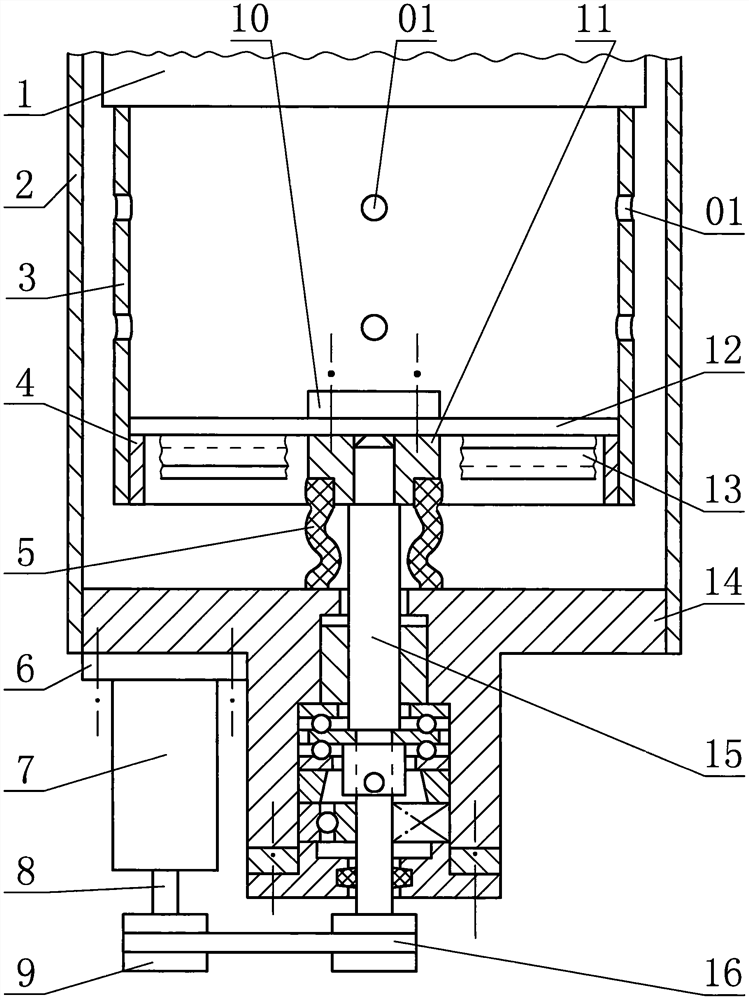
[0067] Those skilled in the art can design many specific implementations based on the technical solution, so the following specific implementations are only examples to illustrate the technical solution. Combine below Figure 1 to Figure 22 , the present invention is further described:

[0068] Figure 1 to Figure 6 and Figure 9 A pulsator washing machine with multiple washing methods is shown, including a tub, a dehydration tub, and a motor. The tub includes side walls and a bottom wall of the tub. The motor is installed on the bottom of the bottom wall of the tub. The motor can rotate in both forward and reverse directions, and the dehydration bucket is located in the water storage bucket. wall, the bottom of the side wall of the dehydration bucket is connected with the bottom wall of the dehydration bucket, and the side wall of the dehydration bucket has a plurality of water holes passing through the inner and outer spaces of the dehydration bucket; the bottom wall of th...


PUM


Abstract

Disclosed is a pulsator washing machine with multiple washing modes. The pulsator washing machine comprises a water containing barrel, a dewatering barrel, a transmission shaft and a motor, and is characterized in that the dewatering barrel side wall and the dewatering barrel bottom wall of the dewatering barrel are provided with a plurality of water holes correspondingly; the middle of the transmission shaft is mounted in a shaft hole in the bottom wall of the water containing barrel; the lower part of the transmission shaft is in transmission relation with the motor; the upper part of the transmission shaft is connected with the dewatering barrel bottom wall; one or more water stirring bodies are arranged on the dewatering barrel or the transmission shaft; when the transmission shaft rotates forwards, the water stirring body drives water in the dewatering barrel to flow into the water containing barrel through water holes in the dewatering barrel side wall and meanwhile drives washing water in the water containing barrel to flow into the dewatering barrel through water holes in the the dewatering barrel bottom wall. when the transmission shaft rotates reversely, the water stirring body drives the washing water in the dewatering barrel to flow into the water containing barrel through the water holes in the dewatering barrel bottom wall and meanwhile drives the washing water in the water containing barrel to flow into the dewatering barrel through the water holes in the dewatering barrel side wall; and the water stirring body drives water to circularly flow in two directions to wash clothes, the efficiency is high, and the effect is good.

Description

technical field [0001] The invention relates to a pulsator washing machine, in particular to a pulsator washing machine with multiple washing modes; the pulsator washing machine mainly relates to the improvement of the transmission system and the washing mode. Background technique [0002] The structure of the existing pulsator washing machine is relatively complicated, resulting in relatively high production costs and a relatively high probability of failure during use, which is reflected in the fact that the dehydration shaft is hollow, the pulsator shaft is installed in the dehydration shaft, and the pulsator is installed on the pulsator shaft When washing, the motor drives the pulsator shaft to rotate through the deceleration clutch, and during dehydration, the motor drives the pulsator shaft and the dehydration shaft to rotate simultaneously through the deceleration clutch; therefore, the power transmission mechanism and its control mechanism are more complicated. The c...

Claims


Application Information

Patent Timeline
Patent Type & Authority Applications(China)
IPC IPC(8): D06F23/04D06F37/12D06F37/14D06F37/40
CPCD06F23/04D06F37/12D06F37/14D06F37/40Y02B40/00
Inventor 柴文龙柴睿明
Owner 柴睿明
Why Eureka
Try Eureka