Railway steel rail center detection vehicle

A technology for detecting vehicles and rails, applied in the field of track detection, can solve the problems of high cost, low measurement accuracy, low work efficiency, etc., and achieve the effects of low cost, high measurement accuracy, and high work efficiency

Pending Publication Date: 2021-05-25
NO 4 ENG CO LTD OF CHINA RAILWAY 11 BUREAU GRP +1
View PDF0 Cites 6 Cited by
  • Summary
  • Abstract
  • Description
  • Claims
  • Application Information

AI Technical Summary

Problems solved by technology

[0003] The purpose of the present invention is to overcome the defects and problems of low measurement accuracy, low work efficiency and high cost in the prior art, and provide a railway rail center inspection vehicle with high measurement precision, high work efficiency and low cost

Method used


Image

  • Railway steel rail center detection vehicle
  • Railway steel rail center detection vehicle
  • Railway steel rail center detection vehicle

Examples


Embodiment 1

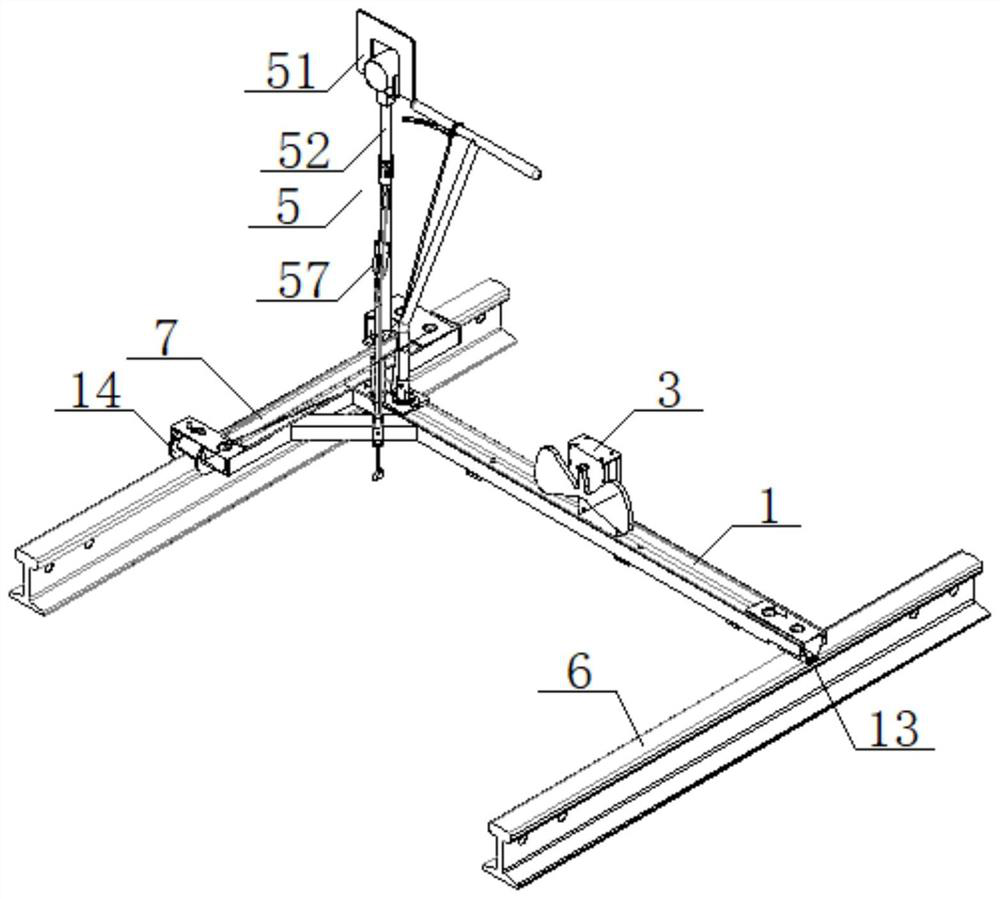
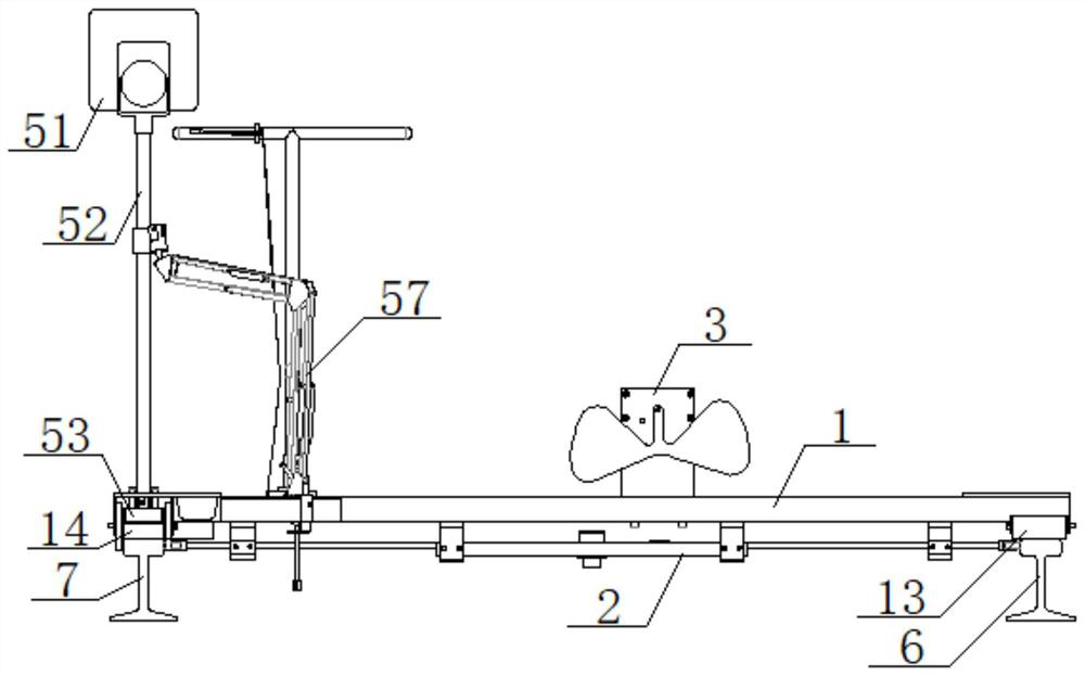
[0067] see Figure 1 to Figure 24 , a railway rail center detection car, comprising a trolley 1 and a No. 1 prism measuring device 5; the trolley 1 includes a connected frame 11 and a push rod 12, and the bottom of one end of the frame 11 is provided with a nylon Wheel 13, nylon wheel 13 is arranged on the left rail 6, and the bottom of vehicle frame 11 other ends is provided with steel channel wheel 14, and steel channel wheel 14 is stuck on the right rail 7; Described No. 1 prism measuring device 5 comprises No. 1 prism 51. The No. 1 prism rod 52 and the joint bearing seat 53, the middle part of the joint bearing seat 53 is provided with a mounting hole 531, and the joint bearing 54 is arranged in the installation hole 531, and the two sides of the joint bearing seat 53 are provided with limited positions. Bolt 55 is arranged in the hole 532, the limit hole 532, and the bolt 55 withstands the joint bearing 54, the joint bearing seat 53 is located directly above the right rai...

Embodiment 2

[0069] Basic content is the same as embodiment 1, the difference is:

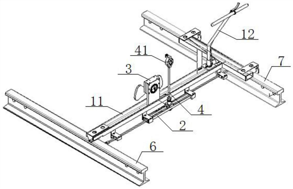
[0070] see Figure 1 to Figure 24 , the vehicle frame 11 is a T-shaped structure, the vehicle frame 11 includes a beam 111 and a longitudinal beam 112, the bottom of one end of the beam 111 is provided with a nylon wheel 13, and the other end of the beam 111 is vertically connected with the longitudinal beam 112, so The longitudinal beam 112 is located directly above the right rail 7, and the bottoms of the two ends of the longitudinal beam 112 are provided with steel sheaves 14, and the push rod 12 is connected with the cross beam 111; the walking trolley 1 also includes a braking device 15, so The brake device 15 includes a brake handle 150, a brake lever 151 and a brake shoe 152. One end of the brake lever 151 is connected to a brake pull pin 153, and the other end of the brake lever 151 is connected to the brake handle 150 through a brake wire 154. Connected, the brake handle 150 is connected with the ...

Embodiment 3

[0072] Basic content is the same as embodiment 1, the difference is:

[0073] see Figure 1 to Figure 24 , the frame 11 is provided with a gauge measuring ruler 2, and the gauge measuring ruler 2 includes a base plate 21, a No. 1 rack 22 and a No. 2 rack 23, and an intermediate gear 24 is arranged at the center of the base plate 21 , the positions on both sides of the intermediate gear 24 on the bottom plate 21 are respectively provided with a No. 1 installation groove 211 and a No. 2 installation groove 212. 24 are engaged with each other, and one end of the No. 1 rack 22 is provided with a mounting column 221, and the No. 1 spring 25 is set on the mounting post 221. The No. 1 spring 25 is fixed in the No. 1 mounting groove 211 through the spring pressing block 26, and the No. 1 rack 22 The other end of the electric insulating bearing 222 is connected with an electrically insulating bearing 27, the scale 223 is set on the No. 1 rack 22, the No. 2 rack 23 is set in the No. 2 ...


PUM


Abstract

A railway steel rail center detection vehicle comprises a walking trolley and a prism measuring device. The walking trolley comprises a frame and a hand push rod, a nylon wheel is arranged at the bottom of one end of the frame and arranged on the left steel rail, and a steel groove wheel is arranged at the bottom of the other end of the frame and clamped on the right steel rail; the prism measuring device comprises a prism, a prism bar and a knuckle bearing seat, a mounting hole is formed in the middle of the knuckle bearing seat, a knuckle bearing is arranged in the mounting hole, limiting holes are formed in the two side faces of the knuckle bearing seat, bolts are arranged in the limiting holes and abut against the knuckle bearing, and the knuckle bearing seat is connected with the frame. One end of the prism bar is connected with the prism, the center of the prism coincides with the center of the right steel rail, the other end of the prism bar is in threaded connection with one end of a prism bar connector, the other end of the prism bar connector is inserted into the knuckle bearing, and a universal support is connected between the prism bar and the frame. The railway steel rail center detection vehicle has the advantages of high measurement precision, high working efficiency and low cost.

Description

technical field [0001] The invention relates to the technical field of track detection, in particular to a railway rail center detection vehicle, which is mainly suitable for improving measurement accuracy, improving work efficiency and reducing costs. Background technique [0002] Because the traditional ballast track measurement operation is to place a prism rod in the center of the rail for measurement, the placement position is estimated by the staff, and the error is relatively large. The prism group is also carried by the staff, so it is laborious; at the same time, the prism bracket is in the ballast. It is not easy to get a foot on it, so the placement speed is slow, and the staff often bend over, and the labor intensity is high and it is easy to get fatigued, so the overall work efficiency is low. At the same time, track fine-tuning requires the use of fine-tuning trolleys, which are expensive and have high rental fees. In addition, the rapid development of railways...

Claims


Application Information

Patent Timeline
Patent Type & Authority Applications(China)
IPC IPC(8): E01B35/02E01B35/04E01B35/08E01B35/10
CPCE01B35/02E01B35/04E01B35/08E01B35/10
Inventor 左小伟王翔袁攀峰宋旭李巍王勇
Owner NO 4 ENG CO LTD OF CHINA RAILWAY 11 BUREAU GRP
Why Eureka
Try Eureka