Construction site dust falling device based on environmental protection
A technology for construction sites and dust suppression devices, which is applied in construction, road surface cleaning, and separation of dispersed particles. It can solve the problems of manpower consumption and achieve good results.
- Summary
- Abstract
- Description
- Claims
- Application Information
AI Technical Summary
Problems solved by technology
Method used
Image

Examples
Embodiment 1
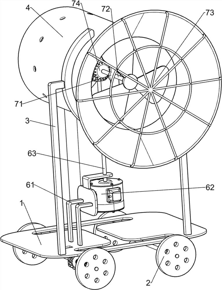
[0031] An environmentally friendly construction site dust suppression device, such as Figure 1-4 As shown, it includes a bottom plate 1, a runner 2, a fixed frame 3, an air duct 4 and a water tank 5. The bottom and front sides of the bottom plate 1 are rotatably connected with the runner 2, and the top and front sides of the bottom plate 1 are connected with a fixed frame. 3. An air duct 4 is arranged between the two fixing frames 3, and a water tank 5 is connected to the left side of the top of the bottom plate 1. The water tank 5 is communicated with the air duct 4, and also includes a driving mechanism 6 and a dust suction mechanism 7. On the bottom plate 1 A driving mechanism 6 is provided, and a dust suction mechanism 7 is arranged in the air duct tube 4 , and the dust suction mechanism 7 is connected with the driving mechanism 6 by transmission.
[0032] The air duct barrel 4 is provided with protrusions, and the protrusions in the air duct barrel 4 are used to block th...
Embodiment 2
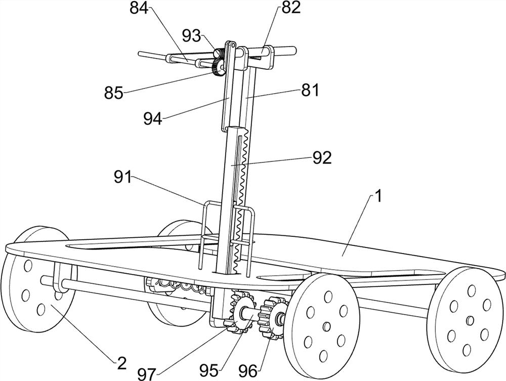
[0037] On the basis of Example 1, as Figure 5 As shown, it also includes a water spray mechanism 8, and the water spray mechanism 8 includes a third support frame 81, a worm 82, a second bevel gear set 83, a second connecting shaft 84, a worm gear 85, a water pump 86 and an annular water spray pipe 87 , a third support frame 81 is connected to the top of the bottom plate 1, a worm 82 is rotatably connected to the third support frame 81, a second bevel gear set 83 is arranged between the worm 82 and the rotating shaft 63, and the third support frame 81 is rotatably connected There is a second connecting shaft 84, a worm gear 85 is connected to the second connecting shaft 84, the worm gear 85 cooperates with the worm 82, a water pump 86 is connected to the top of the water tank 5, the water pump 86 is connected to the second connecting shaft 84 in a driving manner, and the water pump 86 is connected with a ring. The water spray pipe 87 and the annular water spray pipe 87 are sl...
Embodiment 3
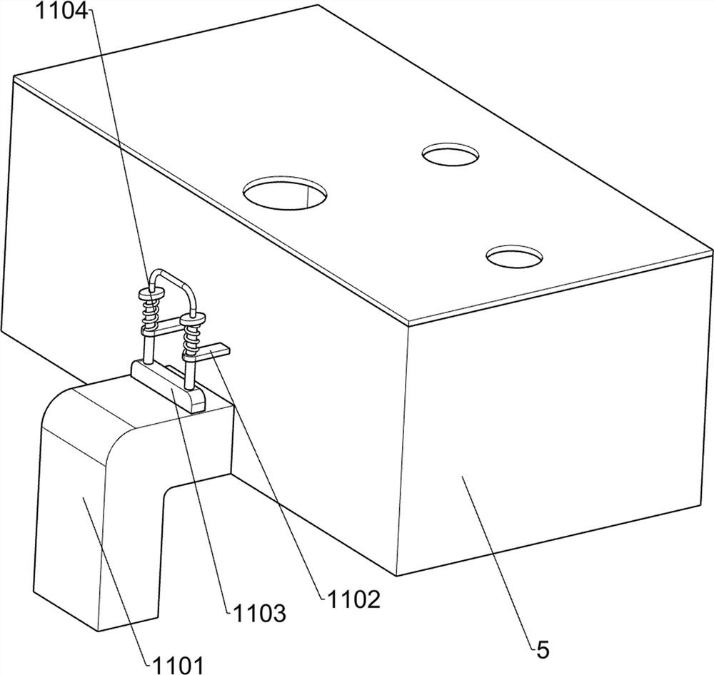
[0042] On the basis of Example 2, such as Figure 7 As shown, a reset mechanism 10 is also included, and the reset mechanism 10 includes a second guide carriage 1001, a guide slider 1002, an iron block 1003, an electromagnet 1004 and a first spring 1005, and the front side of the bottom plate 1 is connected with a second guide Sliding frame 1001, the second sliding guide frame 1001 is slidably connected with a guide slider 1002, the guide slider 1002 is connected with the axle sleeve 95, the guide slider 1002 is connected with an iron block 1003, and the second guide slider 1001 is connected with a An electromagnet 1004, the electromagnet 1004 cooperates with the iron block 1003, and a first spring 1005 is connected between the guide slider 1002 and the second guide carriage 1001.
[0043] When it is necessary to pull the axle sleeve 95 to move to the left, the electromagnet 1004 can be started to energize. After the electromagnet 1004 is energized, the iron block 1003 is suck...
PUM
 Abstract
Description
Claims
Application Information
 - R&D
- Intellectual Property
- Life Sciences
- Materials
- Tech Scout
- Unparalleled Data Quality
- Higher Quality Content
- 60% Fewer Hallucinations
Browse by: Latest US Patents, China's latest patents, Technical Efficacy Thesaurus, Application Domain, Technology Topic, Popular Technical Reports.
© 2025 PatSnap. All rights reserved.Legal|Privacy policy|Modern Slavery Act Transparency Statement|Sitemap|About US| Contact US: help@patsnap.com