Intelligent dust falling device based on plant building

A dust suppression device and intelligent technology, which can be used in construction, use of liquid separators, road cleaning, etc., can solve problems such as unsatisfactory dust suppression effects, and achieve the effect of avoiding excessive waste.

Pending Publication Date: 2021-06-22
DESIGN INST NO 9 MINISTRY OF MECHINE BUILDING
View PDF12 Cites 2 Cited by
  • Summary
  • Abstract
  • Description
  • Claims
  • Application Information

AI Technical Summary

Problems solved by technology

[0006] Aiming at the deficiencies of the prior art, the present invention provides an intelligent dust suppression device based on factory building construction, which has the advantages of removing ground dust, et

Method used


Image

  • Intelligent dust falling device based on plant building
  • Intelligent dust falling device based on plant building
  • Intelligent dust falling device based on plant building

Examples


Embodiment 1

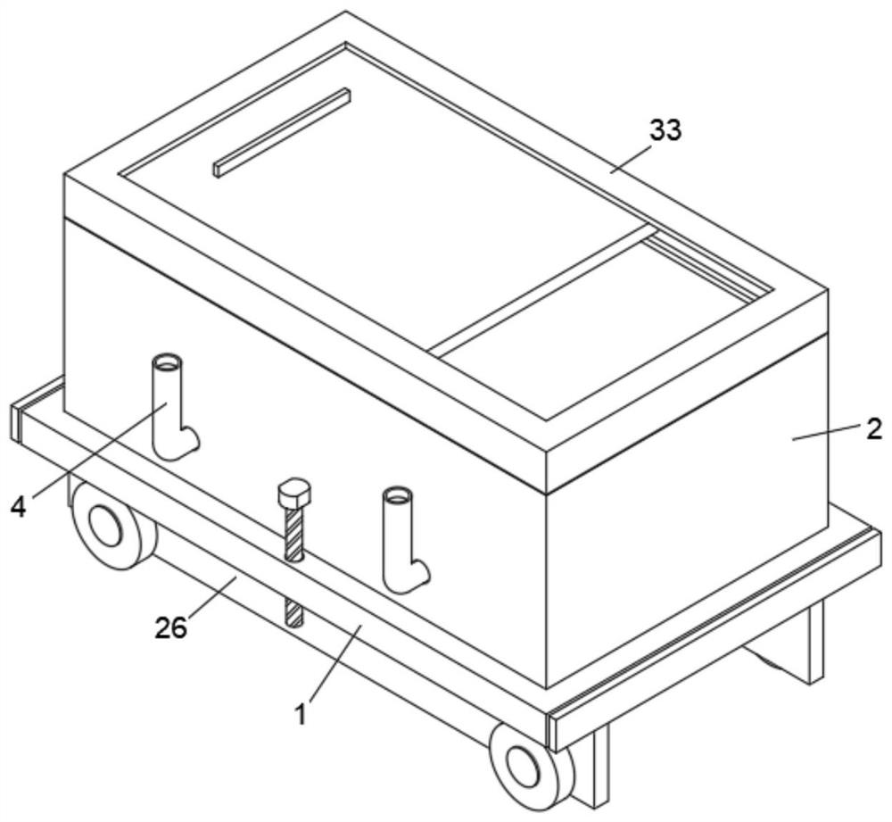
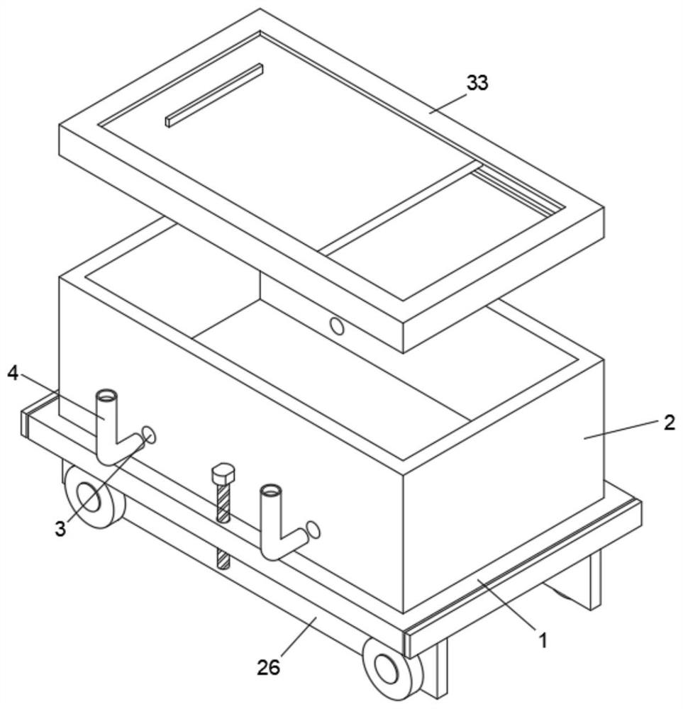
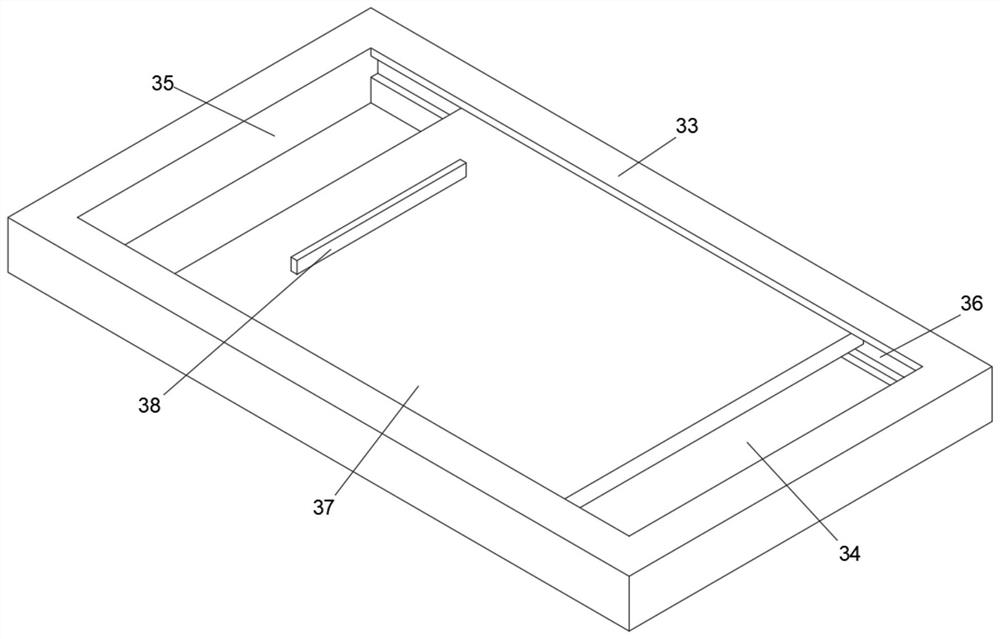
[0036] In a typical implementation of the present application, such as Figure 1-9 As shown, an intelligent dust suppression device based on plant construction includes a base plate 1, the base plate 1 is a rectangular structure, the top surface of the base plate 1 is fixedly equipped with a housing 2, the housing 2 is a rectangular hollow structure, and the top surface of the housing 2 is open. There are two side holes 3 on both sides of the shell 2. The side holes 3 are circular through holes. The inside of the side holes 3 is fixed with a sprinkler pipe 4. The sprinkler pipe 4 is an L-shaped pipe. A small water pump and an atomizer are installed inside. The small water pump and atomizer are prior art and will not be described here. There is a feeding mechanism on the surface. By setting the sprinkling pipe 4, the staff injects the dust-reducing water source into the interior of the casing 2 through the top hole 35, and then starts the small water pump and atomizer inside th...

Embodiment 2

[0041] In order to overcome the deficiencies in the prior art, the present invention also provides an intelligent dust reduction method based on plant construction, the specific steps are as follows:

[0042] S1: first start the small water pump and atomizer inside the sprinkling pipe 4, and the dust in the air outside the device is dedusted by the sprinkling pipe 4, and the first step is completed;

[0043] S2: pull the pull block 23, so that the pull block 23 leaves the inside of the side groove 22, so that the water source inside the shell 2 enters the inside of the bottom pipe 8, and completes the second step;

[0044] S3: The water source hits the rotating plate 21 due to gravity, and the rotating plate 21 drives the rotating block 20 to rotate, disperses the falling water column inside the casing 2, and wets the dust on the ground, completing the third step.

[0045] When in use, by setting the sprinkling pipe 4, the staff injects the dust-reducing water source into the ...


PUM


Abstract

The invention relates to the technical field of building engineering dust falling, and discloses an intelligent dust falling device based on plant building, the intelligent dust falling device comprises a bottom plate, the bottom plate is of a rectangular structure, a shell is fixedly mounted on the top surface of the bottom plate, the shell is of a rectangular hollow structure, two side holes are formed in each of the two sides of the interior of the shell, and the side holes are circular through holes; a water spraying pipe is fixedly installed in the side hole and is an L-shaped pipe, a small water suction pump and an atomizer are arranged in the water spraying pipe, the small water suction pump and the atomizer are not detailed in the prior art, a dust falling mechanism is arranged on the bottom surface of the bottom plate, and a moving mechanism is arranged on the bottom surface of the bottom plate. A feeding mechanism is arranged on the top face of the shell, the water spraying pipe is arranged, a worker injects a dust falling water source into the shell through a top hole, then the small water suction pump and the atomizer in the water spraying pipe are started, the water source in the shell is sprayed upwards, floating dust in the air is adsorbed, the adsorbed dust falls to the bottom surface, and the dust falling effect is achieved.

Description

technical field [0001] The invention relates to the technical field of dust suppression in construction engineering, in particular to an intelligent dust suppression device based on factory building construction. Background technique [0002] Factory building refers to the assets made by man-made construction, which belongs to the category of fixed assets, including two categories of houses and structures. Housing refers to engineering buildings for people to live, work, study, produce, operate, entertain, store items and carry out other social activities. What is different from buildings are structures, which refer to engineering buildings other than houses, such as walls, roads, dams, wells, tunnels, water towers, bridges, and chimneys. [0003] Building construction refers to the production activities in the implementation stage of engineering construction. It is the construction process of various buildings. It can also be said to be the process of turning various lines...

Claims


Application Information

Patent Timeline
IPC IPC(8): B01D47/06E01H3/02E01H1/00
CPCB01D47/06E01H3/02E01H1/00
Inventor 姜博雅崔清秀胡宝忠靳虎芳
Owner DESIGN INST NO 9 MINISTRY OF MECHINE BUILDING
Why Eureka
Try Eureka