New energy photovoltaic panel ash removal device

A cleaning device, a technology of photovoltaic panels, applied in the direction of photovoltaic modules, photovoltaic power generation, cleaning methods and appliances, etc., to achieve the effect of preventing flying around

Active Publication Date: 2022-06-10
湖南福来特新能源开发有限公司
View PDF6 Cites 2 Cited by
  • Summary
  • Abstract
  • Description
  • Claims
  • Application Information

AI Technical Summary

Problems solved by technology

[0005] In order to overcome the shortcomings of the existing technology that the dust cannot be collected while cleaning the dust, and the dust is easy to fly around, which leads to poor cleaning effect, the technology to be solved The problem is: to provide a new energy photovoltaic panel dust removal device that can collect dust while cleaning dust

Method used


Image

  • New energy photovoltaic panel ash removal device
  • New energy photovoltaic panel ash removal device
  • New energy photovoltaic panel ash removal device

Examples


Embodiment 1

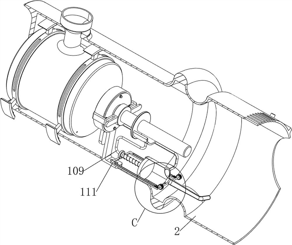
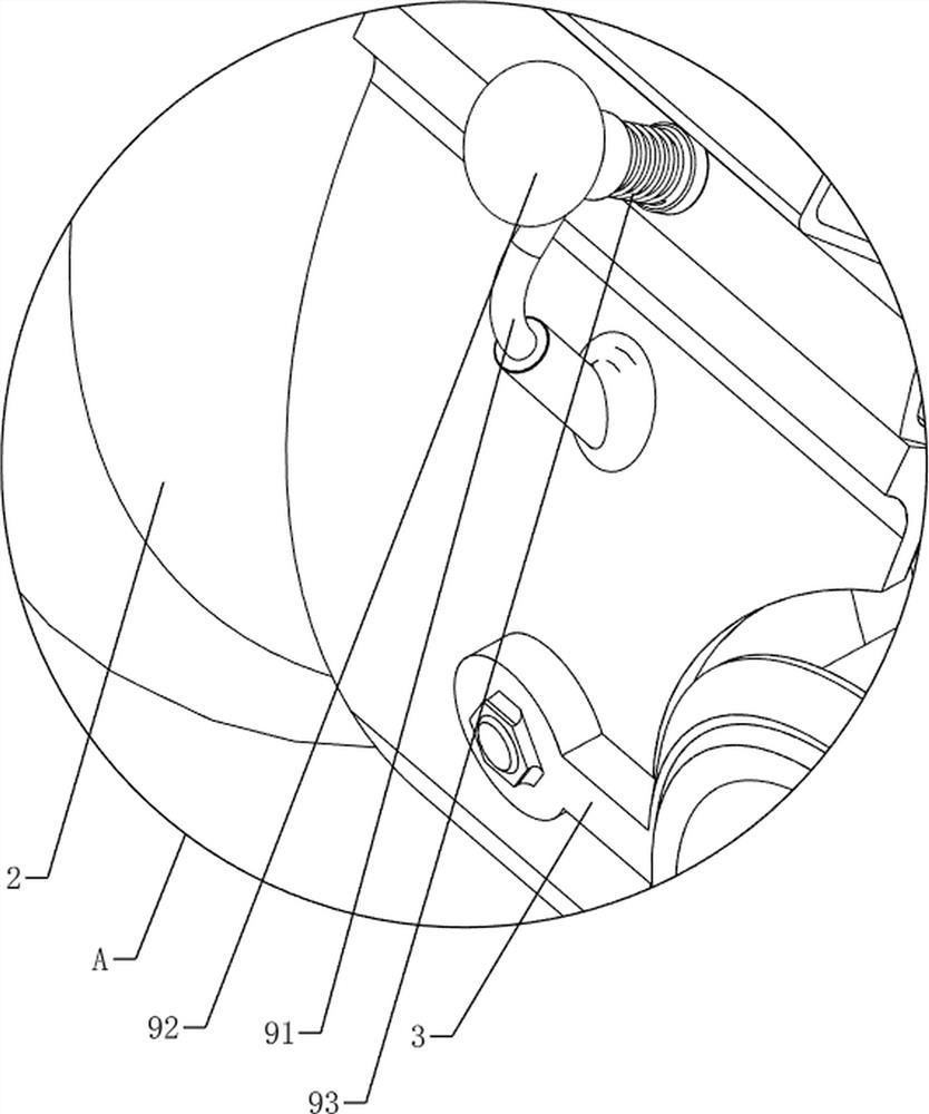
[0038] refer to figure 2 , Figure 10 and Figure 11 , also includes an isolation mechanism 11, the isolation mechanism 11 includes a rack 111, a spur gear 112 and a first baffle plate 113, a rack 111 is provided on the front and rear sides of the bottom of the connecting rod 109, and the middle part of the water injection pipe 106 is rotated. A baffle plate 113, the first baffle plate 113 is used to control the amount of water flowing out, the front and rear sides of the first baffle plate 113 are all keyed with spur gears 112, and the rack 111 meshes with the spur gear 112 on the same side after moving.

[0039] When the connecting rod 109 moves to the right, it further drives the rack 111 to move to the right. When the rack 111 contacts and meshes with the spur gear 112, it further drives the spur gear 112 to rotate, and the spur gear 112 drives the first baffle plate 113 to rotate, making the second A baffle plate 113 no longer closes the water injection pipe 106, and t...

Embodiment 2

[0043] When the sponge 124 is in contact with the photovoltaic panel to absorb water stains, the sponge 124 is squeezed, and then drives the slide bar 122, the rotating drum 123, the sponge 124, the second baffle plate 125, the eighth fixing column 126 and the second push plate 134 to the right Move, the third linear spring 127 is compressed, so that the sponge 124 is in contact with the gathering plate 133, when the sponge 124 rotates, the gathering plate 133 scrapes off the water stains adsorbed on the sponge 124, so that the water stains are concentrated on the gathering plate 133 Conduct flow diversion, while the second push plate 134 moves to the right to contact with the first fork 137 and the second fork 138, and then squeezes the first fork 137 and the second fork 138 to the right, the first fork 137 and the second fork 138 The second fork 138 is opened outwards, the fourth linear spring 136 is compressed, and the first fork 137 and the second fork 138 drive the third b...


PUM


Abstract

The invention relates to an ash removal device, in particular to a new energy photovoltaic panel ash removal device. The invention provides the new energy photovoltaic panel dust removal device capable of collecting dust while removing dust. A new energy photovoltaic panel ash removal device comprises a handle, a main frame body, first fixing columns, fixing frames, second fixing columns, an ash removal barrel, ash removal brushes, an ash removal mechanism and the like, the handle is arranged in the middle of the main frame body, the first fixing columns are arranged on the front side and the rear side of the right side of the main frame body, the fixing frames are arranged on the first fixing columns, and the second fixing columns are arranged on the inner sides of the fixing frames. And a dust cleaning cylinder is rotationally arranged between the second fixing columns, a dust cleaning brush used for cleaning dust on the photovoltaic panel is arranged on the dust cleaning cylinder, and a dust cleaning mechanism is arranged among the main frame body, the fixing frame and the dust cleaning cylinder. Dust on the photovoltaic panel is cleaned through rotation of the dust cleaning brush, the dust attached to the dust cleaning brush is scraped down through the collecting frame to be collected, the dust is prevented from flying around, and then people can clean the dust conveniently.

Description

technical field [0001] The invention relates to a dust removal device, in particular to a new energy photovoltaic panel dust removal device. Background technique [0002] Photovoltaic panels have been exposed to sunlight and rain outdoors for a long time and are polluted by the external environment. The dust pollution layer formed on the surface will greatly reduce the conversion efficiency of photovoltaic cells. [0003] Patent Publication No. CN214211436U discloses a new energy photovoltaic panel cleaning device, including a base, the bottom of the base is fixedly connected with a handle, the outer wall of the handle is fixedly connected with a non-slip cover, and the outer wall of the anti-slip cover is provided with Grab groove, the top of the base is movably connected with a protective shell, one side of the protective shell is provided with a vent, the outer wall of the protective shell is fixedly connected with a female magnet block, and the bottom of the female magne...

Claims


Application Information

Patent Timeline
Patent Type & Authority Applications(China)
IPC IPC(8): B08B1/04B08B13/00F26B5/16F26B5/14H02S40/10
CPCB08B1/002B08B1/04B08B13/00F26B5/16F26B5/14H02S40/10Y02E10/50
Inventor 莫伟
Owner 湖南福来特新能源开发有限公司
Why Eureka
Try Eureka