CO2 micro-explosion combined TBM rock breaking device

A rock-breaking device, CO2 technology, applied in the direction of discharge machinery, mining equipment, earthwork drilling and mining, etc., can solve problems affecting the installation of blasting pipes, uneven sealing of the tunnel surface, etc., to achieve improved continuity, easy operation, and safety sex high effect

Active Publication Date: 2021-05-25
INST OF ROCK & SOIL MECHANICS CHINESE ACAD OF SCI +1
View PDF16 Cites 0 Cited by
  • Summary
  • Abstract
  • Description
  • Claims
  • Application Information

AI Technical Summary

Problems solved by technology

[0003] Moreover, in the prior art, after the rock is broken, the face of the face will be uneven, which will lead to sealing problems. As a result, the gasket of the CO2 blasting device cannot be well sealed with the drilled hole of the face of the face, which will affect the subsequent blasting pipe. installation and other issues

Method used


Image

  • CO2 micro-explosion combined TBM rock breaking device
  • CO2 micro-explosion combined TBM rock breaking device
  • CO2 micro-explosion combined TBM rock breaking device

Examples


Embodiment 1

[0150] In this embodiment, the CO2 micro-explosion combined TBM rock-breaking device 1 includes a cutterhead mechanism 2, a drilling rig installation mechanism 3 and a CO2 blasting device installation mechanism 4; the drilling rig installation mechanism 3 and the CO2 blasting device installation mechanism 4 are alternately arranged on the cutterhead mechanism 2 Above; the cutterhead mechanism 2 is installed on the TBM main bearing; the belt conveyor 5 is installed on the support frame 6; the belt conveyor 5 is located behind the cutterhead mechanism 2.

[0151] The cutterhead mechanism 2 includes a positive cutterhead 2.1 and a side cutterhead 2.2;

[0152] The side cutter head 2.2 is located on the outer periphery of the front cutter head 2.1;

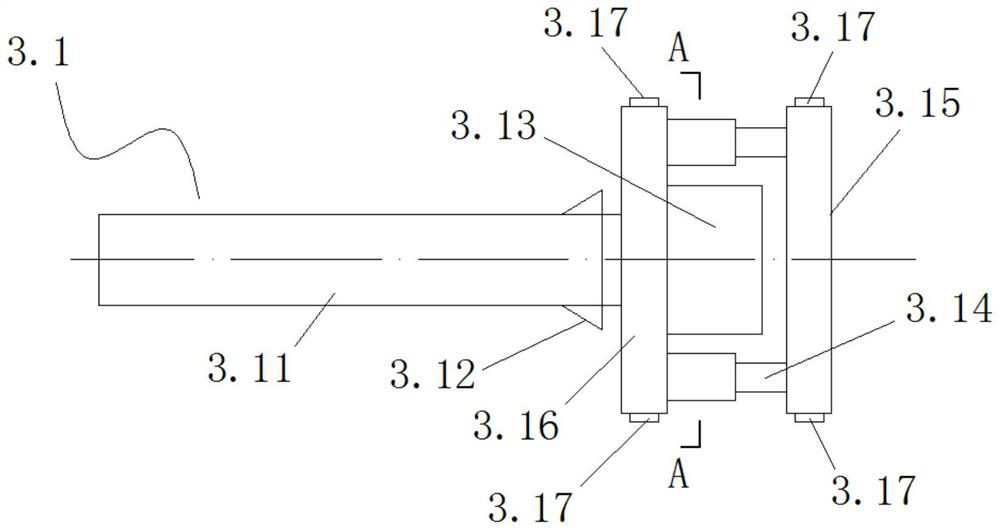
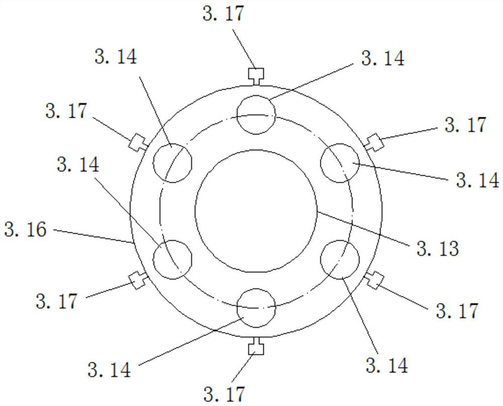
[0153] The drilling rig installation cylinder 3.2 of the drilling rig installation mechanism 3 and the CO2 installation cylinder 4.2 of the CO2 blasting device installation mechanism 4 are alternately arranged on the positive cutter h...

Embodiment 2

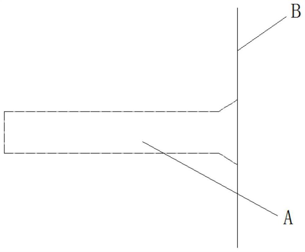
[0164] Its CO2 micro-explosion combined TBM rock-breaking device 1 and its rock-breaking method are the same as in Embodiment 1, the difference is that the rock mass in this embodiment is through a certain blasting and cutting, and the contour of the tunnel surface formed at last is uneven ( As shown in Figure 30), then there is a difference in the stroke of the drilling rod of the drilling rig in the rock mass.

[0165] In this embodiment, a depth measurement sensor is set on the drilling rig (being the prior art); in this embodiment, the depth data of the actual drilling of the drilling rig is obtained by the depth measurement sensor on the drilling rig, and according to the depth data, the next stage CO2 The filling amount of the blasting device and the length of the blasting tube are adjusted; Figure 30 Among them, the actual working footage of the drilling rigs in area A is smaller than the actual working footage of the drilling rigs in area B. The adjustment method in t...

Embodiment 3

[0167] Its CO2 micro-explosion combined TBM rock-breaking device 1 and its rock-breaking method are the same as in Embodiment 2, the difference is that in this embodiment, the contour of the tunnel face is an inclined structure or a rotating structure (such as Figure 31 shown); in Figure 31 Among them, the actual working footage of the drilling rigs in area C is greater than the actual working footage of the drilling rigs in area D. The adjustment method in this embodiment is: when the TBM turns, the drilling length in area C is greater than that in area D. When the CO2 blasting device is in the next stage, The filling amount of CO2 gas is adjusted according to the depth of the drill hole, that is, the length of the CO2 blasting tube and the CO2 filling amount in the C blast hole area are greater than that in the D blast hole area.

[0168] Other unspecified parts belong to the prior art.


PUM


Abstract

The invention discloses a CO2 micro-explosion combined TBM rock breaking device. The CO2 micro-explosion combined TBM rock breaking device comprises a cutterhead mechanism, a drilling machine mounting mechanism and a CO2 blasting device mounting mechanism. The drilling machine mounting mechanism and the CO2 blasting device mounting mechanism are arranged on the cutterhead mechanism. A closed end of a drill hole formed by drilling a rock wall by the drilling machine mounting mechanism is of a cylindrical structure, and an open end is of a conical structure. When a CO2 blasting pipe is mounted, a conical sealing gasket of the CO2 blasting device mounting mechanism is mounted at the open end of the drill hole. The cutterhead mechanism is mounted on a TBM main bearing. A belt conveyor is mounted on a support frame. The belt conveyor is positioned behind the cutterhead mechanism. The CO2 micro-explosion combined TBM rock breaking device has the advantages of being capable of achieving continuous construction, high in construction efficiency, good in rock breaking effect, high in safety and suitable for tunneling construction of hard rocks and extremely-hard rocks.

Description

technical field [0001] The invention relates to the field of tunnels and underground engineering, in particular to the field of TBM tunnel construction under complex geological conditions. More specifically, it is a CO2 micro-explosion combined with TBM rock-breaking device. Background technique [0002] With the advancement of technology, higher requirements are put forward for the construction efficiency and construction effect of hard rock and extremely hard rock TBM tunnel boring machines in different environments. For the excavation of urban hard rock and extremely hard rock, the vibration control requirements of urban surface blasting are high, and traditional explosive blasting has high requirements for use conditions, use environment, and daily management. The rock wears quickly, the frequency of tool change is high, and the economic effect is poor. In addition, for the construction of TBM tunnels with a wide distribution of hard rock and high ecological environmen...

Claims


Application Information

Patent Timeline
Patent Type & Authority Applications(China)
IPC IPC(8): E21D9/00E21D9/10E21D9/12E21C37/14
CPCE21D9/008E21D9/1006E21D9/12E21C37/14
Inventor 周辉李海波徐福通卢景景李彦恒张传庆高阳胡明明崔健
Owner INST OF ROCK & SOIL MECHANICS CHINESE ACAD OF SCI
Why Eureka
Try Eureka