Centrifugal pump for conveying viscous medium

A centrifugal pump and medium technology, which is used in the components of pumping devices for elastic fluids, pumps and pumps for special fluids, etc., which can solve the problem of difficult to guarantee sealing effect and life, poor end-face tracking and fit, and medium liquid film lubrication. It can improve the effect and service life of the mechanical seal, the influence of pressure deformation under working conditions is small, and the anti-torque ability is strong.

Pending Publication Date: 2021-05-25
丹东克隆先锋泵业有限公司
View PDF0 Cites 1 Cited by
  • Summary
  • Abstract
  • Description
  • Claims
  • Application Information

AI Technical Summary

Problems solved by technology

When used to transport viscous and highly adhesive media, it is difficult to form a liquid film because of the high viscosity and poor fluidity of the medium, and the lubricity of the liquid film of the medium is poor, and it is easy to form condensation between the sealing end faces. The sealing end surface is prone to dry grinding, the friction heat is large, the torque is large, and the sealing end surface is easily damaged
[0003] When the conventional mechanical seal device is a spring compensation type, condensation is also likely to be formed at the sliding seal ring, causing the compensation ring to be stuck and the end face to follow poorly.
[0004] When the conventional mechanical seal device is a bellows compensation type, it is also easy to form condensate accumulation in the bellows groove to hinder the compression of the bellows, making the bellows elastically unstable and causing the end surface to follow and fit poorly
[0005] Therefore, it is difficult to guarantee the sealing effect and life of the conventional mechanical seal device. In order to ensure the stability and reliability of the seal, the pump pair needs to be cleaned frequently to remove the condensation on the mechanical seal device. The mechanical seal is frequently repaired and replaced. high cost

Method used


Image

  • Centrifugal pump for conveying viscous medium
  • Centrifugal pump for conveying viscous medium
  • Centrifugal pump for conveying viscous medium

Examples


Embodiment Construction

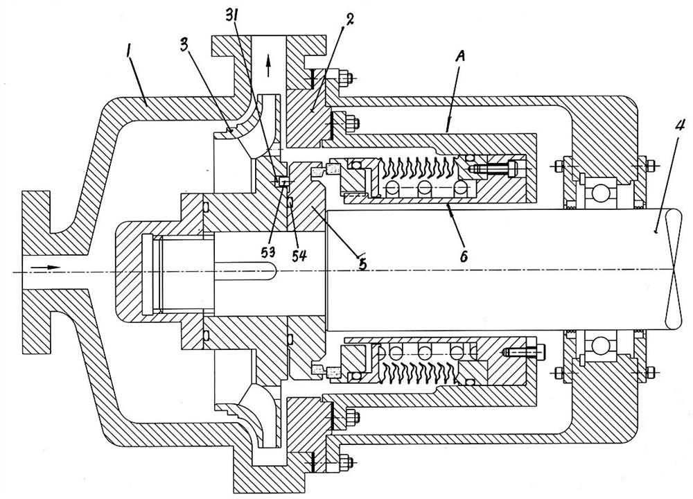
[0033] The present invention is used to convey the centrifugal pump of viscous medium, comprises pump body 1, pump cover 2, impeller 3, pump shaft 4, mechanical sealing device A, mechanical sealing device A is composed of moving ring assembly 5, static ring assembly 6.

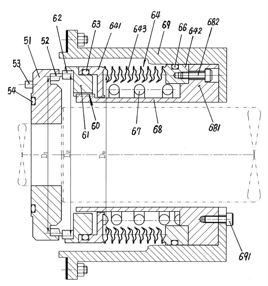
[0034] The moving ring assembly 5 is composed of a moving ring seat 51 , a moving ring 52 , an anti-rotation pin 53 and a sealing ring 54 .

[0035] On the right end surface of the moving ring seat 51, there is an inner stop groove, and the moving ring 52 is embedded and fixedly installed in the inner stop groove provided on the moving ring seat 51, and the moving ring seat 51 is installed on the shaft of the pump shaft 4 through the central shaft hole. At the shoulder, the moving ring seat 51 is axially squeezed and fixed by the impeller 3, and a positioning pin hole 31 is opened on the right end face of the impeller 3, and the anti-rotation pin 53 fixedly installed on the left end face of the moving ring seat...


PUM


Abstract

The invention discloses a centrifugal pump for conveying a viscous medium. The centrifugal pump is mainly characterized in that a static ring assembly for mechanical sealing of the centrifugal pump is composed of a static ring base, a static ring, a static ring base sealing ring, a corrugated pipe assembly, a corrugated pipe front end ring sealing ring, a corrugated pipe rear end ring sealing ring, a compensation spring, a static ring sleeve and a gland; and the columnar compensation spring is installed on the outer circle of the static ring sleeve. The left end pressure of the columnar spring acts on a corrugated pipe front end ring, the corrugated pipe is a large-spacing corrugated pipe, mechanical sealing parameters are set, and the columnar compensation spring is sealed and protected. The corrugated pipe and the columnar spring are combined to provide compensation force, and the phenomenon that the medium forms condensation products in wave plate grooves to affect the telescopic change of the corrugated plate grooves is not likely to occur. The moving end face following fitting performance of the compensation static ring is not affected, the working condition using requirements that the medium viscosity is larger than 10000 CPS, the temperature reaches 275 DEG C and the pressure reaches 2 Mpa can be fully met, the mechanical sealing effect of the centrifugal pump is improved, and the service life of the centrifugal pump is prolonged.

Description

technical field [0001] The patent of the present invention relates to a centrifugal pump and its mechanical sealing device, especially a centrifugal pump used in the working conditions of transporting viscous media such as glue, resin, and rubber, and media with strong adhesion. Background technique [0002] A centrifugal pump includes a pump body, a pump shaft, an impeller, and a mechanical seal. When the centrifugal pump is used in the working condition where the viscosity of the conveying medium is not high, the conventional mechanical seal device can meet the sealing requirements of the centrifugal pump shaft. When used to transport viscous and highly adhesive media, it is difficult to form a liquid film because of the high viscosity and poor fluidity of the medium, and the lubricity of the liquid film of the medium is poor, and it is easy to form condensation between the sealing end faces. The sealing end surface is prone to dry grinding, the friction heat is large, th...

Claims


Application Information

Patent Timeline
IPC IPC(8): F04D7/04F04D7/06F04D29/12
CPCF04D7/04F04D7/06F04D29/126
Inventor 杨春波臧祖玄臧蕴祺周志强丁厉林春阳徐毅何平刘毅于明杨
Owner 丹东克隆先锋泵业有限公司
Why Eureka
Try Eureka