
Rotary power transmission clutch and two-gear speed change regulator

A second-speed variable speed, rotary power technology, applied in transmission control, instruments, controlled components, etc., can solve the problems of high manufacturing cost, limited application, strong use pertinence, etc., to achieve simple and convenient control and operation, and a wide range of applications. , the effect of low manufacturing cost

Pending Publication Date: 2021-05-25
NORTHEAST AGRICULTURAL UNIVERSITY
View PDF0 Cites 0 Cited by
  • Summary
  • Abstract
  • Description
  • Claims
  • Application Information

AI Technical Summary

Problems solved by technology

[0002] The traditional rotary power transmission structure that can be clutched and adjusted by variable speed mostly adopts gear-type gearboxes, which have the advantages of many variable speed gears, but the structure is complex, the manufacturing cost is high, the use is highly targeted, the versatility is poor, and the scope of application is narrow
However, jaw clutches, friction plate clutches, etc., which are solely responsible for rotating power clutch operations, can only undertake clutch control, and cannot complete the transmission adjustment of fewer gears according to the needs of the operation. The adaptability is poor and the application is limited.

Method used


Image

  • Rotary power transmission clutch and two-gear speed change regulator
  • Rotary power transmission clutch and two-gear speed change regulator
  • Rotary power transmission clutch and two-gear speed change regulator

Examples


Embodiment Construction

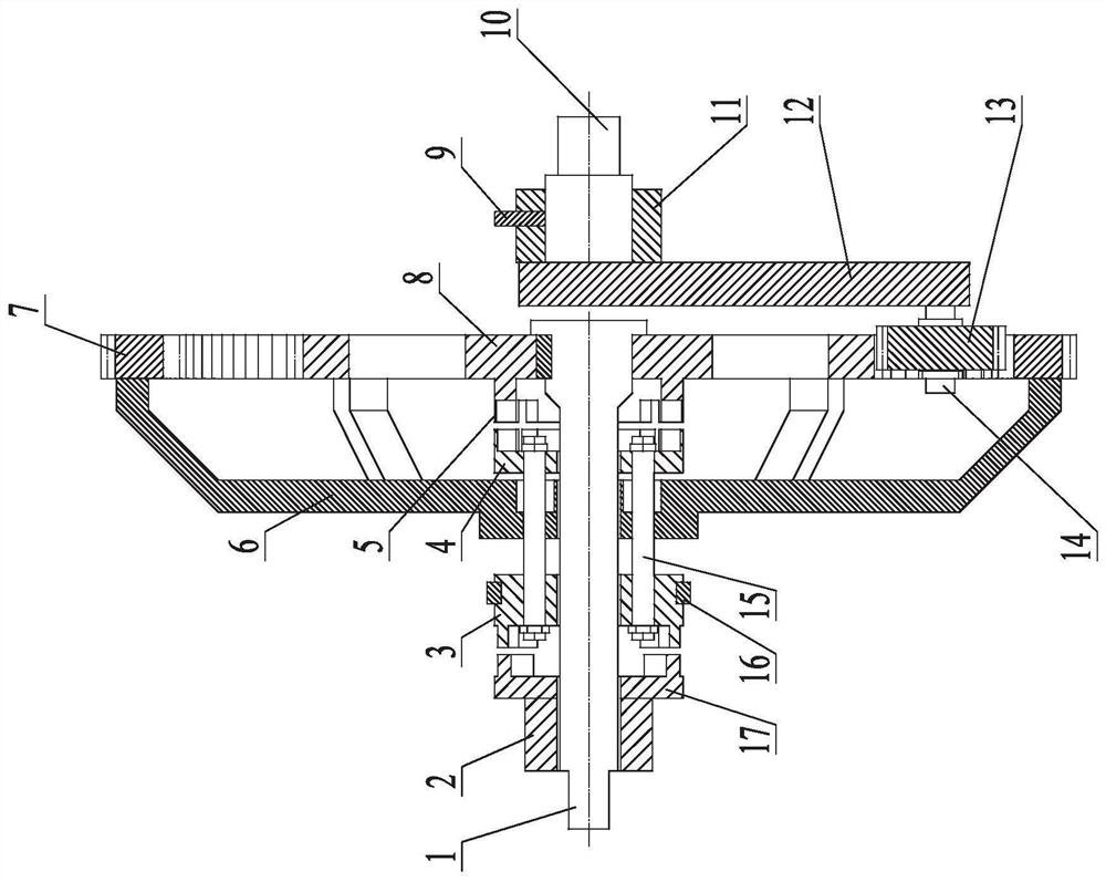
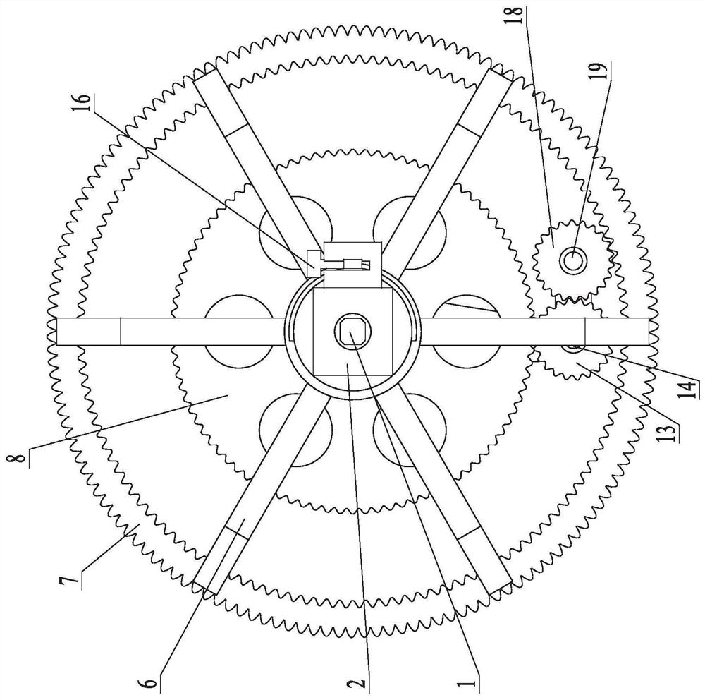
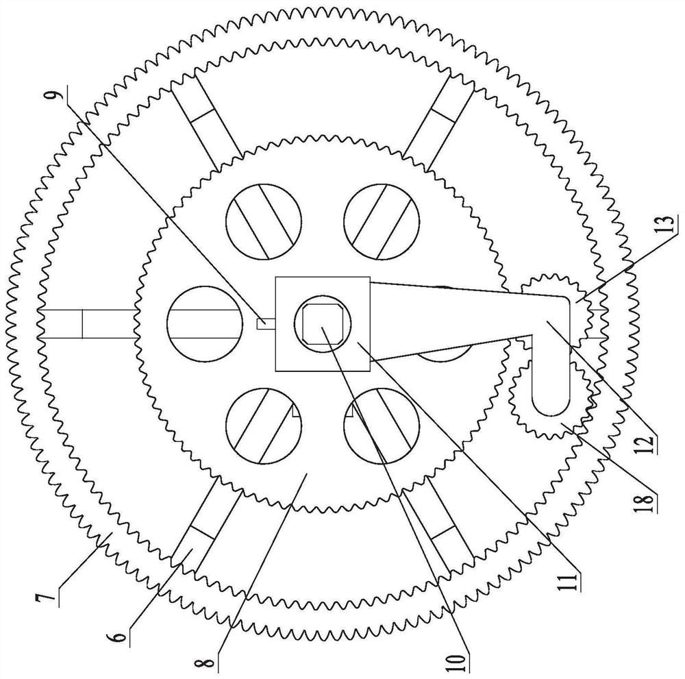
[0014] Embodiments of the present invention will be described in detail below in conjunction with the accompanying drawings. A rotary power transmission clutch and second-speed speed change controller, on a fixedly configured mounting base 2, axially and radially positioned, and circumferentially rotatably inserted into a power input shaft 1, on which the power input shaft 1 is located on the mounting base 2 On the right side, from left to right, the clutch sleeve D17, clutch sleeve C3, driving and locking frame 6, clutch sleeve B4, clutch sleeve A5, and central gear 8 are installed sequentially. The clutch sleeve D17 and the power input shaft 1 are relatively rotatable The ground sleeve fits, and the clutch sleeve D17 is fixedly connected with the mounting seat 2. The clutch sleeve C3 and the clutch sleeve B4 are radially positioned, axially movable left and right, and circumferentially relatively rotatable and sleeved on the power input shaft 1. The driving and locking frame...


PUM


Abstract

The invention relates to a rotary power transmission clutch and two-gear speed change regulator, and belongs to a mechanical transmission mechanism. A power input shaft is rotatably inserted into a fixedly arranged mounting seat; a clutch sleeve D, a clutch sleeve C, a driving and locking frame, a clutch sleeve B, a clutch sleeve A and a central gear are arranged on the power input shaft; the clutch sleeve D is fixedly connected with the mounting seat; the clutch sleeve A is fixed to the central gear; a connecting rod is inserted into the driving and locking frame; two ends of the connecting rod are fixedly connected with the clutch sleeve C and the clutch sleeve B respectively; a shifting fork is clamped on the clutch sleeve C; a supporting shaft sleeved with a supporting sleeve is fixedly arranged on the outer side of the power input shaft; a fastening locking screw is arranged on the supporting sleeve; a planetary gear carrier with a planetary shaft A and a planetary shaft B is fixedly arranged on the supporting sleeve; a planetary gear A and a planetary gear B sleeve the planetary shaft A and the planetary shaft B respectively; and an inner and outer tooth combined power output gear ring fixedly arranged on the driving and locking frame is positioned on the outer side of the planetary gear A. The regulator has a unique, reasonable and compact structure, is easy and convenient to regulate and control, and has a wide application field.

Description

technical field [0001] The invention belongs to a mechanical transmission mechanism, and mainly relates to a rotation power transmission clutch and speed change regulation mechanism. Background technique [0002] The traditional rotary power transmission structure that can be clutched and adjusted by variable speed mostly uses gear-type gearboxes, which have the advantages of multiple shifting gears, but the structure is complex, the manufacturing cost is high, the use is highly targeted, the versatility is poor, and the scope of application is narrow. However, jaw clutches, friction plate clutches, etc., which only undertake rotating power clutch operations, can only undertake clutch control, and cannot complete the speed change adjustment with fewer gears according to the needs of the operation. The adaptability is poor and the application is limited. Therefore, it is very necessary to develop an operation assembly with a simpler structure, more compact dimensions, which c...

Claims


Application Information

Patent Timeline
Patent Type & Authority Applications(China)
IPC IPC(8): F16H61/26F16H63/32F16H1/32
CPCF16H1/32F16H61/26F16H63/32
Inventor 唐汉徐常塑陈君执王金武徐亚男赵剑桥韩宏宇程亨曼
Owner NORTHEAST AGRICULTURAL UNIVERSITY
Learn More