Optical imaging lens

An optical imaging lens, lens technology, applied in optics, optical components, instruments, etc., can solve problems such as poor imaging quality

Pending Publication Date: 2021-05-25
ZHEJIANG SUNNY OPTICAL CO LTD
View PDF0 Cites 4 Cited by
  • Summary
  • Abstract
  • Description
  • Claims
  • Application Information

AI Technical Summary

Problems solved by technology

[0004] The main purpose of the present invention is to provide an optical imaging le

Method used


Image

  • Optical imaging lens
  • Optical imaging lens
  • Optical imaging lens

Examples


Embodiment 1

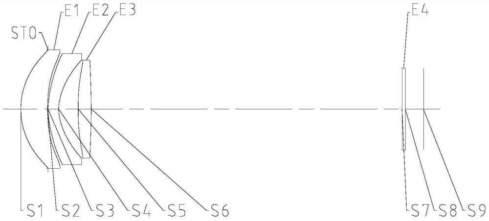
[0050] Such as Figure 1 to Figure 25 As shown, along the optical axis direction of the optical imaging lens, the first lens E1, the second lens E2 and the third lens E3 are sequentially included from the object side to the image side, the first lens E1 has a positive refractive power; the second lens E2 has a negative light Focus; the third lens E3 has positive refractive power; wherein, the effective focal length f of the optical imaging lens satisfies: f>20mm; the effective focal length f of the optical imaging lens and the effective focal length f2 of the second lens satisfy: -3.0

[0051] Through the rational arrangement of the focal power, astigmatism and distortion can be effectively reduced, and the imaging quality of the optical imaging lens can be greatly improved. A lens that uses a combination of positive, negative, and positive can better demonstrate the performance of the optical system. The purpose of reasonably controlling the effective focal leng...

Embodiment 2

[0066] The optical imaging lens includes a first lens E1, a second lens E2 and a third lens E3 in sequence from the object side to the image side along the optical axis of the optical imaging lens. The first lens E1 has a positive refractive power; the second lens E2 has a negative optical power. focal length; the third lens E3 has a positive refractive power; wherein, the effective focal length f of the optical imaging lens satisfies: f>20mm; the effective focal length f of the optical imaging lens and the maximum half field of view Semi-FOV of the optical imaging lens meet : 2.5

[0067] Through the rational arrangement of the focal power, astigmatism and distortion can be effectively reduced, and the imaging quality of the optical imaging lens can be greatly improved. A lens that uses a combination of positive, negative, and positive can better demonstrate the performance of the optical system. The purpose of reasonably controlling the effective focal ...


PUM


Abstract

The invention provides an optical imaging lens. The optical imaging lens sequentially comprises, from an object side to an image side in the optical axis direction of the optical imaging lens, a first lens having positive focal power; a second lens having negative focal power; and a third lens having positive focal power. The effective focal length f of the optical imaging lens meets f>20 mm; and the effective focal length f of the optical imaging lens and the effective focal length f2 of the second lens meet the following formula: -3.0<f/f2<-2.0 . According to the invention, the problem of poor imaging quality of a camera lens in the prior art is solved.

Description

technical field [0001] The present invention relates to the technical field of optical imaging equipment, in particular to an optical imaging lens. Background technique [0002] With the development of science and technology, the miniaturization trend of camera lenses has become more and more obvious. As we all know, the more pixels of CMOS (Complementary Metal Oxide Semiconductor), the greater the magnification of the photos taken, and this principle can be used to crop the imaged picture by using algorithms when shooting with large CMOS , so that only a part of the image is displayed and enlarged to form a zoom effect. This method of zooming is also called digital zooming. The disadvantage of this method is that the more the image is enlarged, the fewer pixels there are, and the blurrier the photo. [0003] That is to say, the imaging lens in the prior art has the problem of poor imaging quality. Contents of the invention [0004] The main purpose of the present inven...

Claims


Application Information

Patent Timeline
IPC IPC(8): G02B13/00G02B13/18
CPCG02B13/0035G02B13/18
Inventor 孔旭乐闻人建科胡亚斌戴付建赵烈烽
Owner ZHEJIANG SUNNY OPTICAL CO LTD
Why Eureka
Try Eureka