
Electric connector with structure convenient to install

A technology for installing electrical connectors and joints, which is applied in the direction of connection and connection device parts, circuits, etc., can solve the problems of affecting the normal use of electrical connectors, falling off of electrical connectors, cumbersome disassembly and assembly, etc., and achieves convenient disassembly and assembly. Increased stability and strong plugging effect

Inactive Publication Date: 2021-05-25
吉安市联基电子有限公司
View PDF0 Cites 0 Cited by
  • Summary
  • Abstract
  • Description
  • Claims
  • Application Information

AI Technical Summary

Problems solved by technology

[0003] At present, the electrical connectors produced on the market are fixed by screws or directly plugged together. When the electrical connectors need to be replaced and repaired, the disassembly and assembly are cumbersome. When the electrical connectors are subjected to external force , the electrical connector is very easy to fall off, which affects the normal use of the electrical connector. Therefore, it is necessary to improve the installation structure of the electrical connector. At the same time, the invention proposes an electrical connector with a structure that is easy to install, so as to better solve the above problems. proposed question

Method used


Image

  • Electric connector with structure convenient to install
  • Electric connector with structure convenient to install
  • Electric connector with structure convenient to install

Examples


Embodiment Construction

[0027] In order to make the object, technical solution and advantages of the present invention clearer, the present invention will be further described in detail below in conjunction with the accompanying drawings and embodiments. It should be understood that the specific embodiments described here are only used to explain the present invention, not to limit the present invention.

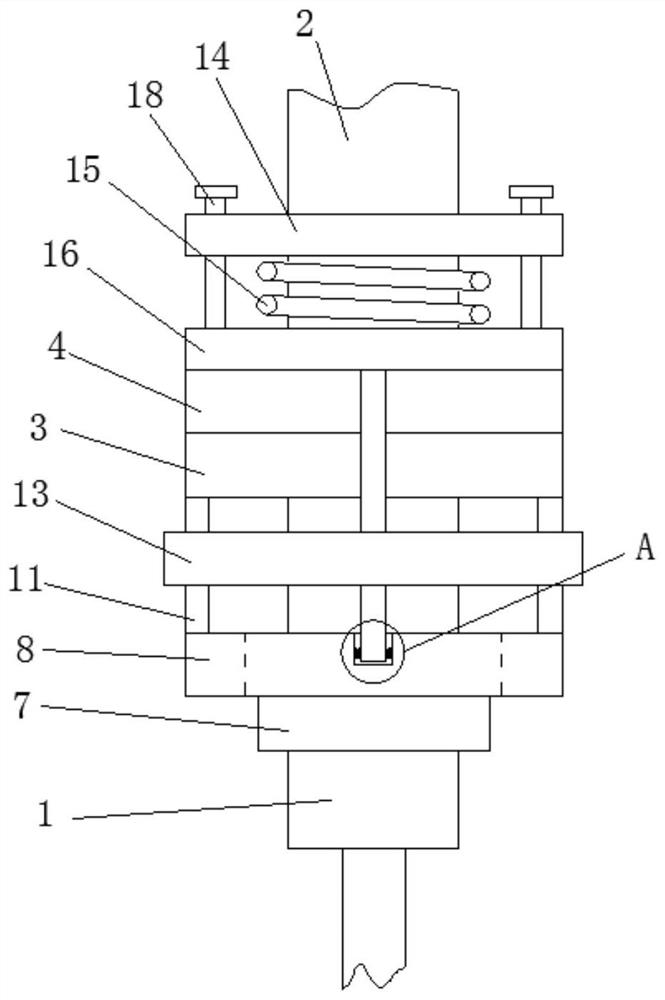
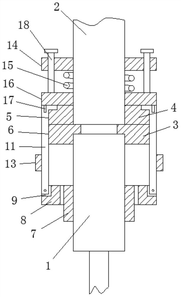
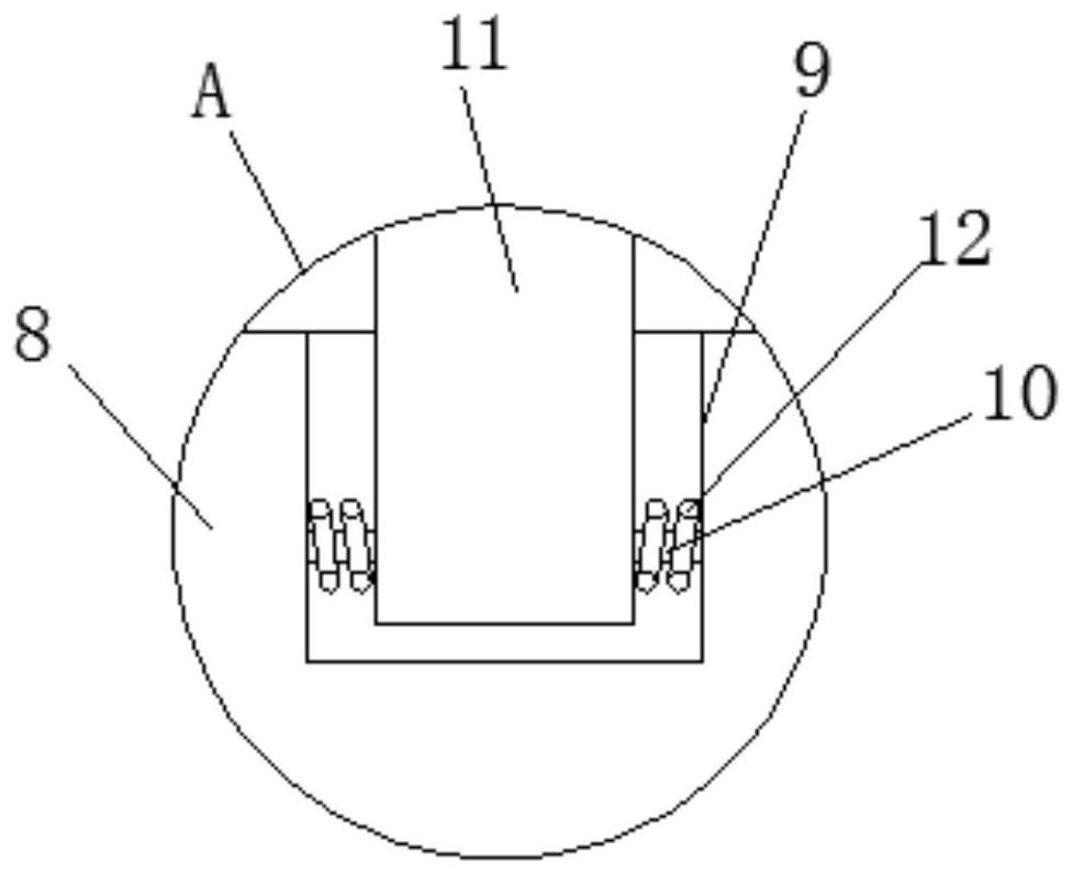
[0028] refer to Figure 1-6, an electrical connector with a structure that is easy to install, including an electrical connector body 1, the outer wall of the electrical connector body 1 is a threaded structure, a mounting joint body 2 is plugged into the top of the electrical connector body 1, and the electrical connector body 1 A mounting joint body 2 is fixedly mounted on the top, a first flange 3 is fixedly mounted on the electrical connector body 1, a second flange 4 is fixedly mounted on the mounting joint body 2, the first flange 3 and the second method The blue plates 4 are bonded together...


PUM


Abstract

The invention discloses an electric connector with a structure convenient to install, which comprises an electric connector body. An installation joint body is inserted into the top of the electric connector body, the installation joint body is fixedly installed on the electric connector body, a first flange plate is fixedly installed on the electric connector body, and a second flange plate is fixedly installed on the first flange plate. A first flange plate is fixedly mounted on the mounting connector body, a second flange plate is fixedly mounted on the mounting connector body, the first flange plate and the second flange plate are attached together, a limiting groove is formed in the periphery of the first flange plate, a positioning groove is formed in the periphery of the second flange plate, and a positioning drag hook is conveniently limited in the limiting groove. The positioning grooves are formed in the positions, opposite to the limiting grooves, of the periphery of the second flange plate, the positioning pull hooks can be clamped and hooked in the positioning grooves conveniently, the first flange plate and the second flange plate can be extruded together, and the stability when the electric connector body and the installation connector body are connected in an inserted mode is improved.

Description

technical field [0001] The invention belongs to the technical field of connectors, in particular to an electrical connector with a structure that is convenient for installation. Background technique [0002] In various electronic systems of weaponry, electrical connectors perform electrical connection and signal transmission between devices and devices, components and components, systems and systems, and are the basic components necessary to form a complete system. In addition to meeting the general performance requirements, the particularly important requirement is that the electrical connector must achieve good contact, reliable operation, and easy maintenance. Whether its operation is reliable or not directly affects the normal operation of the aircraft circuit and involves the safety of the entire host. In various military aircraft and weaponry, the amount of electrical connectors is relatively large, especially the amount of electrical connectors used on aircraft is ver...

Claims


Application Information

Patent Timeline
Patent Type & Authority Applications(China)
IPC IPC(8): H01R13/639
CPCH01R13/639
Inventor 韩林肖萍招陈才华彭全衍
Owner 吉安市联基电子有限公司
Learn More