
A vertical assembly device for the same groove of the rotor magnets of the permanent magnet motor of the rail transit

A permanent magnet motor and rail transit technology, applied in the field of rail transit permanent magnet motor rotor magnetic steel vertical assembly device in the same groove, to achieve the effect of easy type change, low cost and simple structure

Active Publication Date: 2022-07-19
襄阳中车电机技术有限公司 +1
View PDF0 Cites 0 Cited by
  • Summary
  • Abstract
  • Description
  • Claims
  • Application Information

AI Technical Summary

Problems solved by technology

[0003] The technical problem to be solved by the present invention is to overcome the deficiencies of the prior art, to provide a method that can control the initial position of each piece of magnetic steel after it is inserted into the rotor core, and ensure that two adjacent pieces of magnetic steel will not collide when they are assembled into the iron core. Vertical assembly device for rail permanent magnet motor rotor magnets in the same slot, which solves the problem that the initial distance of the magnets into the rotor core slot is uncontrollable, causing damage to two adjacent pieces of magnets due to collision

Method used


Image

  • A vertical assembly device for the same groove of the rotor magnets of the permanent magnet motor of the rail transit
  • A vertical assembly device for the same groove of the rotor magnets of the permanent magnet motor of the rail transit
  • A vertical assembly device for the same groove of the rotor magnets of the permanent magnet motor of the rail transit

Examples


Embodiment Construction

[0023] The present invention will be further described in detail below with reference to the accompanying drawings and specific embodiments.

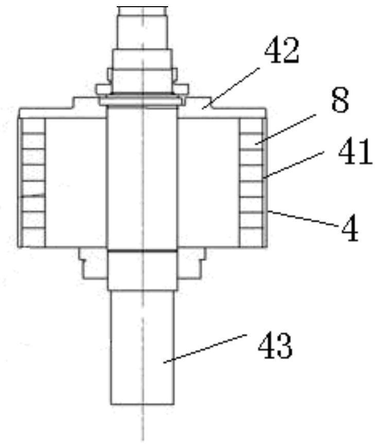
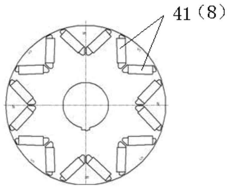
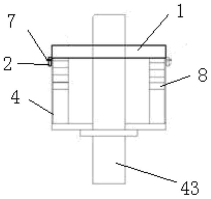
[0024] like Figure 3 to Figure 5 As shown in the figure, the vertical assembly device for the magnetic steel of the rotor of the permanent magnet motor for rail transit in this embodiment includes a magnetic steel assembly guide mold 1 and an iron ring 2, and the magnetic steel assembly guide mold 1 is provided with a plurality of magnetic steels along the circumferential direction. Slot 3, the two sides of the magnetic steel slot 3 are respectively provided with a first auxiliary slot 51 and a second auxiliary slot 52. The first auxiliary slot 51 and the second auxiliary slot 52 are connected with the magnetic steel slot 3. The first auxiliary slot There is a first iron block 61 in the 51, a second iron block 62 is arranged in the second auxiliary groove 52, the width of the first iron block 61 and the second iron block 62 in the circ...


PUM


Abstract

The invention discloses a vertical assembly device for magnetic steel with the same groove of the rotor of a permanent magnet motor for rail transit, which comprises a magnetic steel assembly guide die and an iron ring. The two sides of the slot are respectively provided with a first auxiliary slot and a second auxiliary slot, the first and second auxiliary slots are connected with the magnetic steel slot, the first auxiliary slot is provided with a first iron block, and the second auxiliary slot is arranged in A second iron block is provided, the widths of the first and second iron blocks in the circumferential direction are different, and the iron ring can be sleeved on the outer circumference of the rotor iron core and fixed with the rotor iron core. The invention combines the iron ring and the first iron block and the second iron block with different widths, so that the magnetic steel is adsorbed and stayed at a specific position under the action of unbalanced magnetic force, so that it can control the magnetic steel after each piece of magnetic steel is inserted into the rotor core. The initial position of the magnetic steel ensures that the adjacent two pieces of magnetic steel will not collide when they are assembled into the iron core, which solves the problem that the initial distance of the magnetic steel into the iron core slot is uncontrollable, causing the collision and damage of the adjacent two pieces of magnetic steel.

Description

technical field [0001] The invention relates to the technical field of manufacture of permanent magnet motors, in particular to a vertical assembly device of a permanent magnet motor rotor magnet steel in the same groove for rail transit. Background technique [0002] During the production process of the rotor of the permanent magnet motor, the main problem facing the assembly of samarium cobalt magnetic steel is that when the magnetic steel is assembled, two adjacent pieces of magnetic steel collide and are damaged. In order to improve the efficiency of the subway permanent magnet motor rotor magnetic steel assembly, the qualified rate of the magnetic steel assembly, and the consistency of the magnetic steel assembly quality, the overall structure of the subway permanent magnet traction motor rotor core is commonly used in the manual magnetic steel assembly scheme: same-slot assembly / same-slot assembly Pole assembly / same layer assembly, the efficiency of the three assembly ...

Claims


Application Information

Patent Timeline
Patent Type & Authority Patents(China)
IPC IPC(8): H02K15/00H02K15/03
CPCH02K15/00H02K15/03
Inventor 何维刘刚雷军曾凡军元炯李爱华肖敬义
Owner 襄阳中车电机技术有限公司
Learn More