Adjustable punching equipment for wood board
A kind of punching equipment and adjustable technology, which can be applied to fixed drilling machines and other directions, and can solve the problems of not being able to drill two holes on a wooden board, and not being able to adjust the distance of the punching holes.
- Summary
- Abstract
- Description
- Claims
- Application Information
AI Technical Summary
Problems solved by technology
Method used
Image

Examples
Embodiment 1
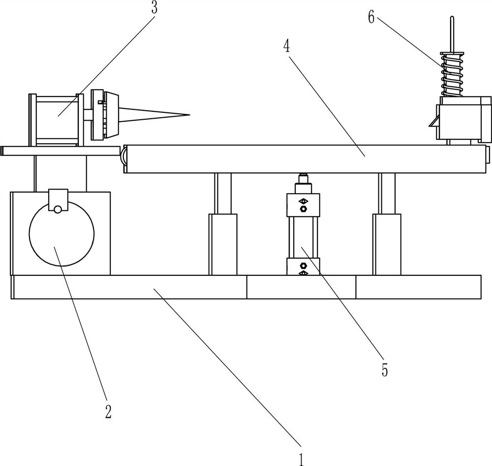
[0027] An adjustable punching device for planks such as figure 1 As shown, it includes a base 1 , an adjustment mechanism 2 and an opening mechanism 3 . The adjustment mechanism 2 is installed on the left side of the top of the base 1 , and two opening mechanisms 3 are arranged on the adjustment mechanism 2 .
[0028] When it is necessary to use the present invention to punch a wooden board, the user adjusts the positions of the two hole opening mechanisms 3 through the adjustment mechanism 2. Then the user moves the wooden board to the left and makes holes on the wooden board through the hole opening mechanism 3. In this way, the purpose of opening two holes at a time can be realized, and by adjusting the positions of the two hole opening mechanisms 3, different holes can be realized. For the opening of the distance, when the opening of the plank is completed, the user can move the plank away from the opening mechanism 3 .
Embodiment 2
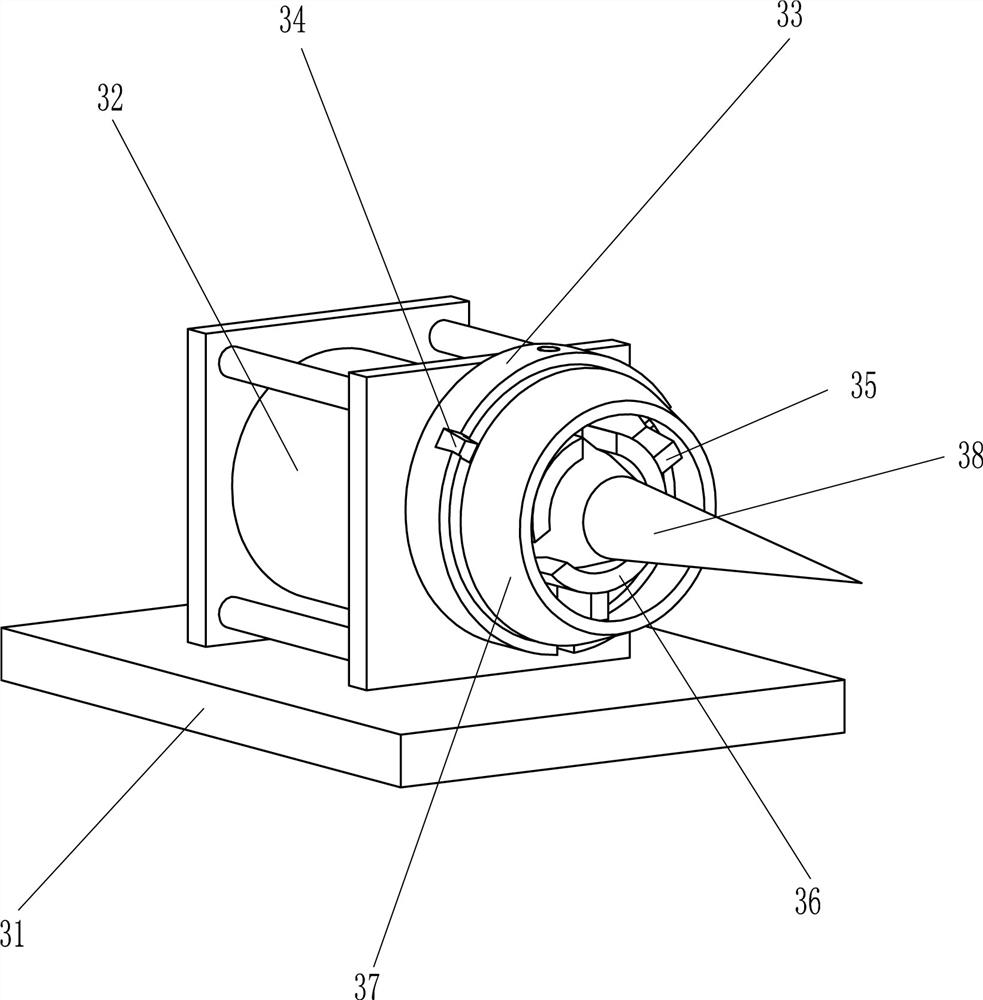
[0030] On the basis of Example 1, such as figure 1 and figure 2 As shown, the adjustment mechanism 2 includes a placement groove 21, a screw mandrel 22, a sliding nut 23, a rocker 24 and a clamping plate 25. The placement groove 21 is installed on the left side of the top of the base 1, and the placement groove 21 is provided with a screw rod 22. The screw mandrel 22 is provided with two sliding nuts 23 through threaded connection, the sliding nuts 23 are slidably matched with the placement groove 21, the front end of the screw rod 22 is fixed with a rocking handle 24, and the front side wall upper part of the placement groove 21 is rotationally connected. There is clamping plate 25, and clamping plate 25 cooperates with rocking handle 24.
[0031] Before the plank needs to be drilled, the user swings the clamping plate 25 upwards to remove the fixing of the rocking handle 24, and then the user rotates the screw mandrel 22 clockwise or counterclockwise through the rocking ha...
Embodiment 3
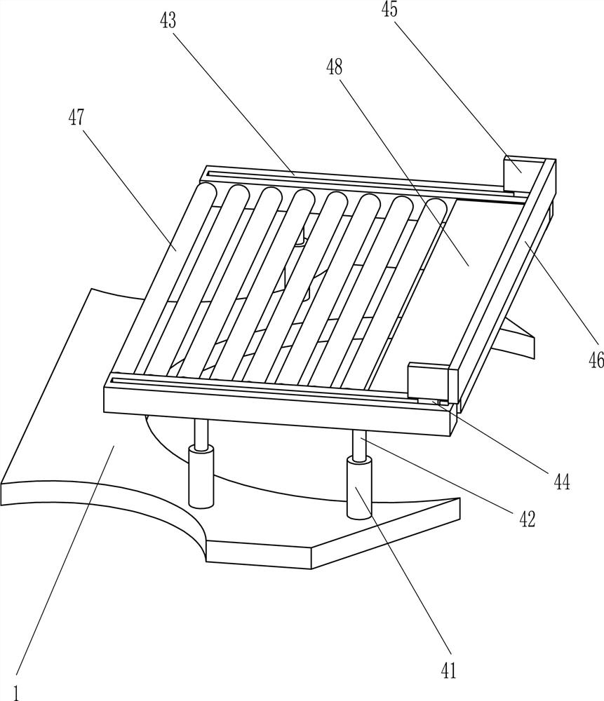
[0035] On the basis of Example 2, such as figure 1 and Figure 4As shown, a placement mechanism 4 is also included, and the placement mechanism 4 includes a slide tube 41, a slide bar 42, a slide rail 43, a slider 44, a connecting plate 45, a push plate 46, a rotating roller 47 and a placement plate 48, and the top of the base 1 Two sliding tubes 41 are installed on the front and rear sides of the front and rear sides, and the sliding tube 41 is located on the right side of the placement groove 21. A sliding rod 42 is provided in the sliding type in the sliding tube 41, and a sliding rod 42 is fixedly connected between the two adjacent sliding rods 42 on the left and right. Rail 43, sliding type is provided with slide block 44 on slide rail 43, and connecting plate 45 is installed on the slide block 44, is fixedly connected with push plate 46 between the right side wall of front and back two connecting plates 45, two slide rails 43 At least five rollers 47 are rotatably arran...
PUM
 Abstract
Description
Claims
Application Information
 - R&D Engineer
- R&D Manager
- IP Professional
- Industry Leading Data Capabilities
- Powerful AI technology
- Patent DNA Extraction
Browse by: Latest US Patents, China's latest patents, Technical Efficacy Thesaurus, Application Domain, Technology Topic.
© 2024 PatSnap. All rights reserved.Legal|Privacy policy|Modern Slavery Act Transparency Statement|Sitemap