
Device for assisting injection molding machine in demolding injection product

A technology for injection molding products and injection molding machines, which is applied in the field of devices for assisting the ejection of injection molding products of injection molding machines. It can solve problems such as increased safety hazards, unsatisfactory demoulding effects, and mismatched sizes, so as to achieve smooth demoulding and demoulding of ejector pins. The effect of convenient and fast work

Inactive Publication Date: 2021-05-28
施诞
View PDF0 Cites 2 Cited by
  • Summary
  • Abstract
  • Description
  • Claims
  • Application Information

AI Technical Summary

Problems solved by technology

[0002] Demolding refers to a series of operations that remove the injection molded object from the ingot mold. On traditional injection molding machines, injection molding and demoulding are completed step by step, and sometimes even after the injection molding of the injection molding machine is completed, it needs to be processed by an external machine or It is a manual way to assist demoulding. The former may not match the size of the injection molding machine when the machine is demoulding, resulting in unsatisfactory demoulding effect, or directly damaging the object that has been injection molded. The latter is manually operated. When demoulding, due to the high temperature in the mold after injection, it is very likely to burn the staff and increase the safety hazard. Therefore, we have proposed a device to assist the demoulding of the injection molding product of the injection molding machine to solve the above problems

Method used


Image

  • Device for assisting injection molding machine in demolding injection product
  • Device for assisting injection molding machine in demolding injection product
  • Device for assisting injection molding machine in demolding injection product

Examples


Embodiment Construction

[0021] The following will clearly and completely describe the technical solutions in the embodiments of the present invention with reference to the accompanying drawings in the embodiments of the present invention. Obviously, the described embodiments are only some, not all, embodiments of the present invention. Based on the embodiments of the present invention, all other embodiments obtained by persons of ordinary skill in the art without making creative efforts belong to the protection scope of the present invention.

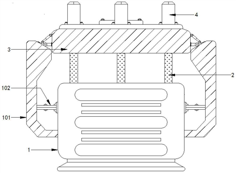
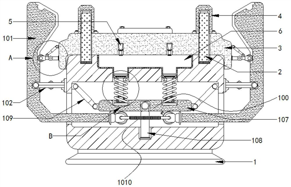
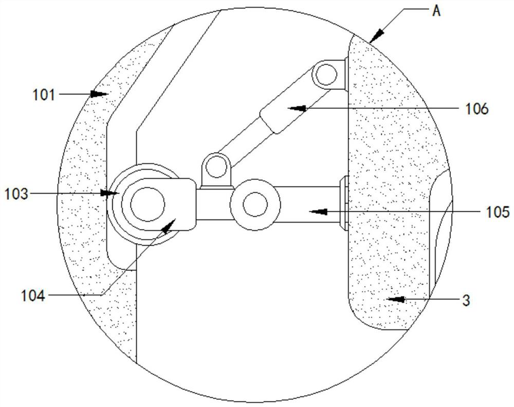
[0022] see Figure 1-2 , a device for assisting the ejection of injection molded products of an injection molding machine, including a base 1 and a demoulding assembly 100, characterized in that: the inner wall of the top of the base 1 is fixedly equipped with an electric telescopic rod 2, and the numbers of the electric telescopic rod 2 and the fixed column 4 are respectively There are four, each electric telescopic rod 2 and fixed column 4 form a group, each...


PUM


Abstract

The invention relates to the technical field of injection molding auxiliary demolding devices, and discloses a device for assisting an injection molding machine in demolding an injection product. The device comprises a base and a demolding component, wherein electric telescopic rods are fixedly arranged on the inner wall of the top of the base; an injection molding table is movably connected to the outer wall of the electric telescopic rod; all structures in the demolding component are matched for use, so that after injection molding is completed, once the injection molding table ascends, a formed object in a mold can be pushed out, and the demolding work is more convenient and faster; through the cooperation of all structures in a rolling wheel component, when swing rods drive a supporting disc to enable ejector rods to demold the object, the ejector rod does not ascend stably and rotates along with the rotation of two second pulleys, and ejector pins in the two second pulleys are controlled to be ejected out in a staggered mode, so that a supporting plate is pushed to swing and ascend like a seesaw, the ejector rods are further made to swing leftwards and rightwards around the center of the supporting plate, the object in the mold is pushed out of the mold and moves upwards in a staggered mode, and it is guaranteed that the ejector rods can conduct demolding more smoothly.

Description

technical field [0001] The invention relates to the technical field of injection molding auxiliary demoulding devices, in particular to a device for assisting the demoulding of injection molded products of an injection molding machine. Background technique [0002] Demolding refers to a series of operations that remove the injection molded object from the ingot mold. On traditional injection molding machines, injection molding and demoulding are completed step by step, and sometimes even after the injection molding of the injection molding machine is completed, it needs to be processed by an external machine or It is a manual way to assist demoulding. The former may not match the size of the injection molding machine when the machine is demoulding, resulting in unsatisfactory demoulding effect, or directly damaging the object that has been injection molded. The latter is manually operated. When demolding, due to the high temperature in the mold after injection, it is very li...

Claims


Application Information

Patent Timeline
Patent Type & Authority Applications(China)
IPC IPC(8): B29C45/40
CPCB29C45/4005
Inventor 施诞
Owner 施诞
Learn More