Wool coagulator

A wool condensing device and condensing technology, applied in the direction of fiber opening and cleaning machines, etc., can solve problems such as unfavorable textile production, low efficiency, and textile entanglement

Pending Publication Date: 2021-05-28
青岛诚利佳机械有限公司
View PDF0 Cites 0 Cited by
  • Summary
  • Abstract
  • Description
  • Claims
  • Application Information

AI Technical Summary

Problems solved by technology

[0003] The invention discloses a hair condenser to solve the problems in the prior art that the hair condenser has co

Method used


Image

  • Wool coagulator
  • Wool coagulator
  • Wool coagulator

Examples


Embodiment Construction

[0030] Below in conjunction with specific embodiment the present invention is described in further detail:

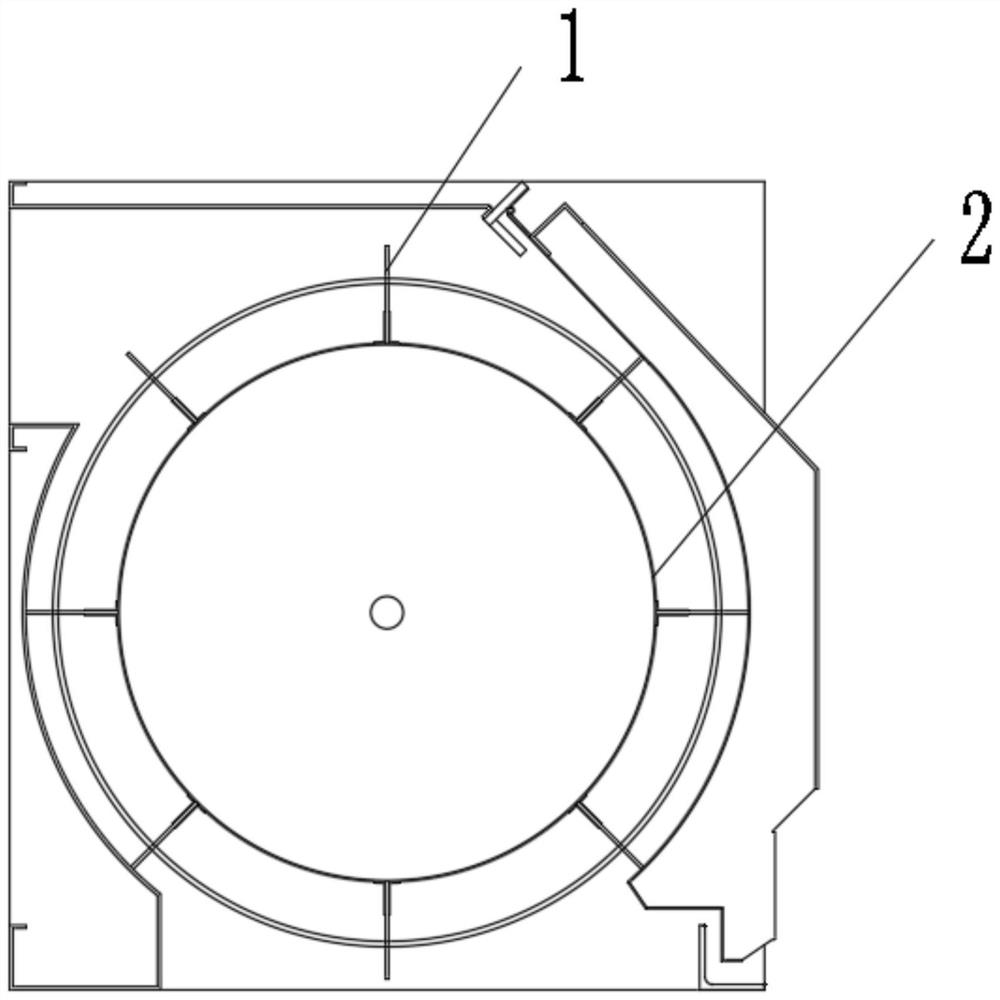
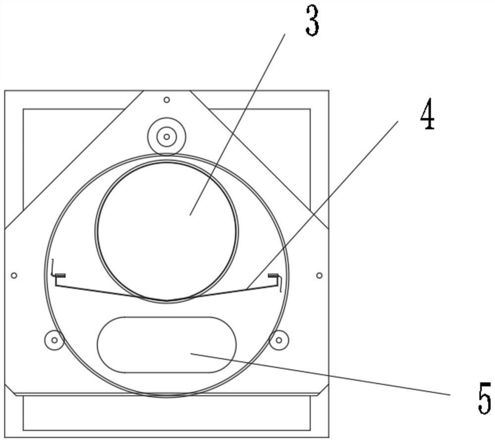
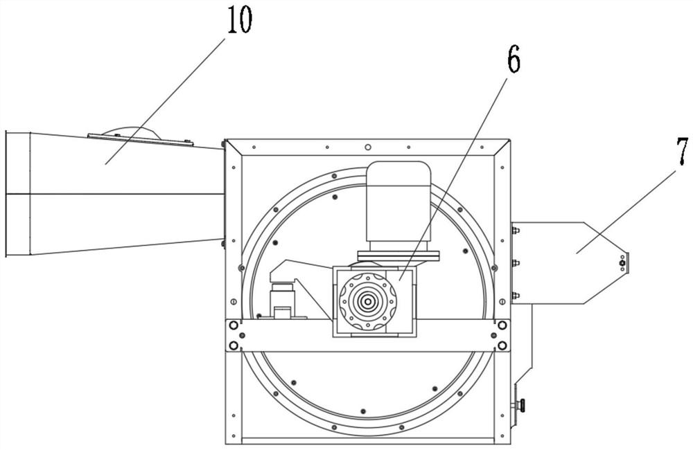
[0031] A hair condenser, comprising a shell, a feed port 10, a dust cage, a dust cage 2, a reducer 6, an air suction port 3, a windshield 4 and an air supply port;

[0032] The shell is a cuboid, with a feed inlet 10 on the top of the front, a reducer 6 on the first side, an air suction port 3 on the second side, a dust cage inside the shell, and a dust cage inside the dust cage. The placed cylindrical dust cage 2 is provided with a windshield 4 inside the dust cage 2 .

[0033] The length of the dust cage 2 is the same as that of the casing;

[0034] One side of the dust cage 2 is provided with a rotating plate, and the center of the rotating plate is provided with a connecting shaft connected with the reducer 6;

[0035] One end of the windshield 4 is fixed on the connecting shaft through a bearing, and the other end is fixedly connected to the second side of the ho...


PUM


Abstract

The invention discloses a wool coagulator, and belongs to the technical field of textile machinery. The wool coagulator comprises a shell, a feeding hole, a dust cage cylinder, a dust cage, a speed reducer, an air suction hole, an air baffle and an air supplement hole, wherein the shell is a cuboid; the feeding hole is formed in the top of the front face of the shell; the speed reducer is arranged on a first side face of the shell; the air suction hole is formed in a second side face of the shell; the dust cage cylinder is arranged in the shell; the cylindrical dust cage arranged in the axial direction is arranged in the dust cage cylinder; the air baffle is arranged in the dust cage; the dust cage is as long as the shell; a rotating plate is arranged on one side of the dust cage; a connecting shaft connected with the speed reducer is arranged in the center of the rotating plate; one end of the air baffle is fixed to the connecting shaft through a bearing, and the other end of the air baffle is fixedly connected with the second side face of the shell; the air baffle is flush with the bottom of the air suction hole; the center of the air baffle is sunken downwards; and a mesh plate is arranged at the air supplement hole. According to the invention, a textile is separated under the action of gravity, the efficiency is high, and textile entanglement is not prone to occurring; and the arranged air supplement hole can effectively avoid the problem of no falling due to negative pressure below the air baffle.

Description

technical field [0001] The invention discloses a hair condenser, which belongs to the technical field of textile machinery. Background technique [0002] The transportation of textile products from the "textile pile" to the "conveyor line" has always been a research hotspot in textile machinery. The hair condenser in the prior art is usually equipped with a "plucking" device at the bottom of the dust cage to remove the textiles on the surface of the dust cage. Pulling up and down the dust cage, this device has a complex structure and low efficiency, and is prone to entanglement of textiles, which is not conducive to high-efficiency textile production. In order to solve this problem, the present invention proposes a device without "plucking hair" hair condenser. Contents of the invention [0003] The invention discloses a wool condenser to solve the problems in the prior art that the wool condenser has complex structure, low efficiency, easy occurrence of textile entanglem...

Claims


Application Information

Patent Timeline
IPC IPC(8): D01G9/14
CPCD01G9/14
Inventor 张耀亮
Owner 青岛诚利佳机械有限公司
Why Eureka
Try Eureka