Threshing device

A technology of threshing device and threshing chamber, which is applied in threshing equipment, application, agricultural machinery and implements, etc. It can solve problems such as entanglement of grain stalks, reduction of threshing performance and conveying performance, and deformation of shielding plates, so as to increase the amount of grain leakage , Improve rigidity and prevent deformation

Active Publication Date: 2015-11-18
ISEKI & CO LTD
View PDF8 Cites 0 Cited by
  • Summary
  • Abstract
  • Description
  • Claims
  • Application Information

AI Technical Summary

Problems solved by technology

[0007] However, in the threshing drum of Patent Document 1, there is a possibility that the harvested long grain stalks are entangled with the cross member, and the threshing performance and the backward conveyance performance may be reduced.
[0008] In addition, in the threshing drum of Patent Document 2, when a large amount of grain stalks are supplied to the front part of the threshing drum, since the support members are arranged at the front end, the middle part, and the rear end, there is a possibility that the threshing The shield plate at the front of the drum deforms due to the reaction force received from the grain stalks, reducing the threshing performance and rearward conveyance performance

Method used


Image

  • Threshing device
  • Threshing device
  • Threshing device

Examples


no. 2 Embodiment approach

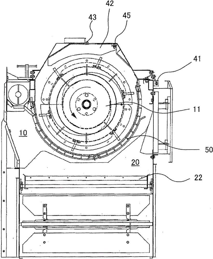
[0135] Next, the barrel 11 of 2nd Embodiment is demonstrated in detail. In addition, the same reference numerals are assigned to the same members, and overlapping explanations are omitted.

[0136] The distance between the threshing gears 78A of the plate 78 and the distance between the threshing gears 79A of the plate 79 attached adjacent to the outer peripheral surface of the cylindrical part 17 is to efficiently carry the grain stalks backward and improve the filtration rate from the threshing net 50 . ,Such as Figure 19 As shown, the distance between the processing teeth 78A and 79A erected on the front side of the plates 78 and 79 is twice the interval of the processing teeth 78A and 79A erected on the rear side of the plates 78 and 79 . In addition, about the processing teeth 78A and 79A of the plates 78 and 79 that are adjacently installed, the phases are shifted on the front side, and the processing teeth 78A and the processing teeth 79A are arranged so as not to ove...

no. 3 Embodiment approach

[0138] Next, the barrel 11 of 3rd Embodiment is demonstrated in detail. In addition, the same code|symbol is attached|subjected to the same member, and repeated description is abbreviate|omitted.

[0139] In order to prevent the threshing teeth 88 and 89 from being entangled by the supplied grain stalks, improve the threshing performance, and carry out the conveyance of the grain stalks to the rear efficiently, such as Figure 20 As shown, on the front side of the cylinder part 17, it is alternately arranged at intervals of 90 degrees in the circumferential direction: a plate 88 with a threshing tooth 88A is erected; and a plate 89 with a threshing tooth 89A is erected. The rear side part is provided alternately at intervals of 60° in the circumferential direction: the plate 88 provided with the processing gear 88A standing up; and the plate 89 provided with the processing gear 89A standing up. In addition, in 3rd Embodiment, the interval of 88 A of processing teeth and the i...


PUM


Abstract

PURPOSE: A threshing apparatus is provided to prevent the deformation of a body part of a threshing drum and to maintain high threshing performance. CONSTITUTION: A threshing apparatus(17) comprises a threshing drum having a drum body that is installed by a drum shaft(12) between a front plate and a rear plate of a threshing chamber. A threshing net(50) is lengthwise installed on the circumference of the threshing drum. A selecting room having a fluctuation selecting apparatus is included at a lower part of the threshing chamber. The threshing drum comprises a front part supporting member that supports the front part of the drum body to the front part of the drum shaft, a rear part supporting member that supports the rear part of the drum body to the rear part of the drum shaft, and a middle part supporting member that supports the middle part in back and forth directions of the drum body to the drum shaft.

Description

technical field [0001] The invention relates to a threshing device with a threshing drum. Background technique [0002] In the past, in order to reduce the burden of production work, a kind of threshing device has been proposed, which has a threshing cylinder. The said support member is being fixed to the front-end part, the intermediate part, and the rear end part of the drum shaft extended in the front-back direction of a machine body (refer patent document 1). [0003] In addition, a threshing device has been proposed, which has a threshing cylinder configured by erecting a crosspiece member provided with threshing teeth in the front-rear direction on the apex of a substantially hexagonal support member, and closing the threshing cylinder with a shielding plate. The said support member is being fixed to the front-end|tip part, the middle part, and the rear end part of the barrel shaft extended in the front-back direction of a machine body in the clearance gap between the...

Claims


Application Information

Patent Timeline
Patent Type & Authority Patents(China)
IPC IPC(8): A01F12/22A01F12/18
CPCA01F12/18A01F12/32A01F12/44
Inventor 饭泉清石川道男大崎正美秋山尚文田上和成橘弥沙松田善正
Owner ISEKI & CO LTD
Why Eureka
Try Eureka