A transmission tower pile foundation with adjustable anti-pulling and anti-extrusion properties
A transmission tower and anti-pulling technology, applied in infrastructure engineering, construction, protection devices, etc., can solve the problem of increasing the inclination of the transmission tower pile foundation to the inside of the turn, reducing the reliability of the transmission tower pile foundation, and making it difficult to ensure the safety of power grid operation. and other problems, to achieve the effect of saving maintenance costs, saving construction period and shortening construction period
- Summary
- Abstract
- Description
- Claims
- Application Information
AI Technical Summary
Problems solved by technology
Method used
Image
Examples
Embodiment 1
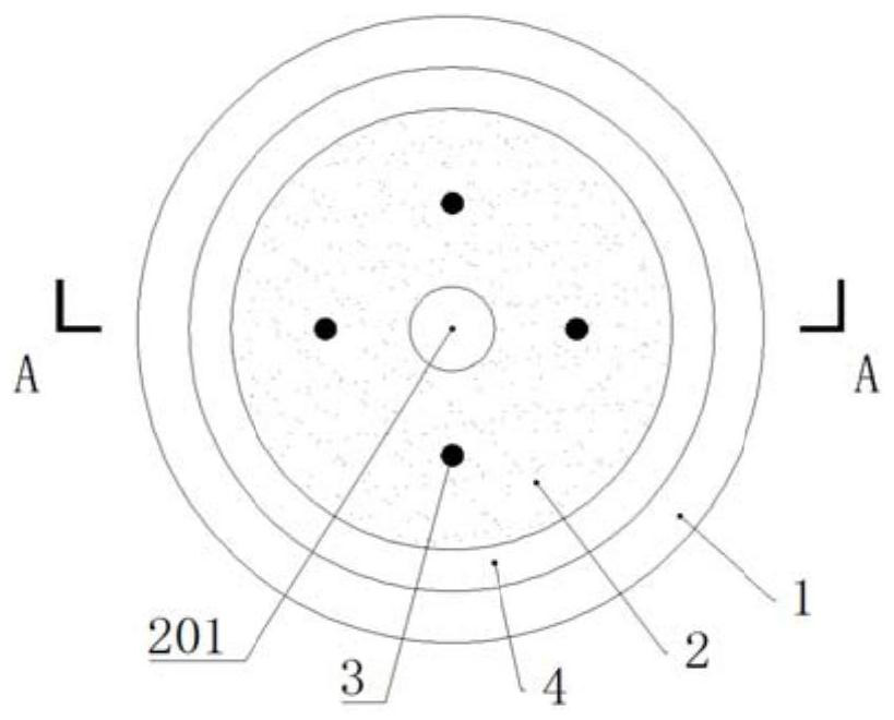
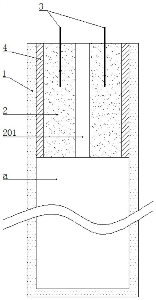
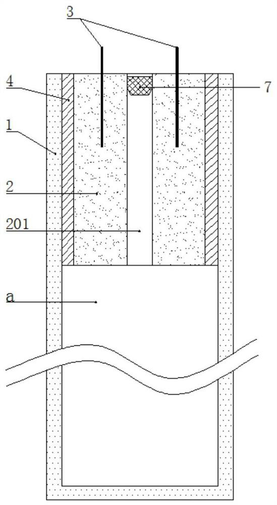
[0045] like Figure 1-4 As shown, a transmission tower pile foundation with adjustable anti-pulling and anti-extrusion performance includes a support cylinder 1, a concrete pier 2, a fastener 3, a sealing layer, a connecting pipe 5, an air pressure adjusting device, and a blocking member.
[0046] The upper end surface of the support cylinder 1 is open.
[0047] Fasteners 3 are embedded in the concrete pier 2. The fasteners are anchor bolts that are convenient for the staff to obtain materials. The upper part of the anchor bolts exposes the upper end face of the concrete pier 2. The anchor bolts are used to fix the lower end of the transmission tower. On the upper end face of concrete pier 2.
[0048] The concrete pier 2 is installed in the support cylinder 1 , and the concrete pier 2 is provided with a ventilation hole 201 . For the convenience of description, the cavity in the support cylinder 1 located between the concrete pier 2 and the cylinder bottom of the support cyl...
Embodiment 2
[0059] The present embodiment 2 makes the following improvements on the basis of embodiment 1:
[0060] like Figure 5-9 As shown, the second embodiment no longer uses the rubber plug 7 as the blocking member, but uses the one-way valve 8 as the blocking member. The check valve 8 is installed in the vent hole 201 . The one-way valve 8 is a common valve body 801 in the market, which is convenient to obtain. The one-way valve 8 includes a valve body 801 and a valve core 802 installed in the valve body 801. When there is no external force acting on the valve core 802, the valve core 802 is pushed up by the elastic member 803 installed in the one-way valve 8 to close the valve body At the inlet 8011 of 801, the elastic member 803 adopts a spring with convenient material. When the valve core 802 is squeezed by an external force, the valve core 802 overcomes the elastic force of the elastic member 803 to open the inlet 8011, and the fluid can flow through the inlet 8011 of the val...
Embodiment 3
[0067] The present embodiment 3 makes the following improvements on the basis of embodiment 2:
[0068] like Figure 10 As shown, the vent hole 201 is provided with a mounting pipe 10, and the mounting pipe 10 is fixed in the inner wall of the vent hole 201 by screws. The one-way valve 8 is arranged in the installation pipe 10 , and the valve body 801 of the one-way valve 8 is welded and fixed to the inner wall of the installation pipe 10 . The inner wall of the installation pipe 10 is provided with internal threads, and the outer pipe wall of the end of the connecting pipe 5 close to the concrete pier 2 is provided with external threads.
[0069] When connecting the connecting pipe 5 and the cavity between the concrete pier 2 and the bottom of the supporting cylinder 1, the staff can directly screw the end of the connecting pipe 5 with the connecting plate 9 into the installation pipe 10 until it is at the connecting point. It is sufficient that the pressing protrusion 902 ...
PUM
 Abstract
Description
Claims
Application Information
 - R&D
- Intellectual Property
- Life Sciences
- Materials
- Tech Scout
- Unparalleled Data Quality
- Higher Quality Content
- 60% Fewer Hallucinations
Browse by: Latest US Patents, China's latest patents, Technical Efficacy Thesaurus, Application Domain, Technology Topic, Popular Technical Reports.
© 2025 PatSnap. All rights reserved.Legal|Privacy policy|Modern Slavery Act Transparency Statement|Sitemap|About US| Contact US: help@patsnap.com


