A Microstructured Optical Fiber Broadband Polarization Filter with Tunable Filtering Direction

A technology of micro-structure optical fiber and polarization filter, which is applied in the field of optical fiber communication, can solve the problems of non-adjustable polarization filtering direction and inability to satisfy the adjustment of polarization direction, etc., and achieves the advantages of increased resonance peak, simple structure, and high orthogonal polarization loss ratio Effect

Active Publication Date: 2022-04-29
广州大鱼创福科技有限公司
View PDF16 Cites 0 Cited by
  • Summary
  • Abstract
  • Description
  • Claims
  • Application Information

AI Technical Summary

Problems solved by technology

However, the optical fiber structure with broadband single-polarization filter transmission completed by the existing technical scheme has only a single or two resonance wavelengths, and a single or two resonance peaks appear, realizing the design of a broadband polarization filter
At the same time, in the prior art, after the structure of the microstructured optical fiber is determined, to complete the expected broadband polarization filter, the coating position is fixed and cannot be tuned, and the polarization filtering direction is also non-adjustable, which cannot meet the requirement of adjustable polarization direction

Method used


Image

  • A Microstructured Optical Fiber Broadband Polarization Filter with Tunable Filtering Direction
  • A Microstructured Optical Fiber Broadband Polarization Filter with Tunable Filtering Direction
  • A Microstructured Optical Fiber Broadband Polarization Filter with Tunable Filtering Direction

Examples


Embodiment 1

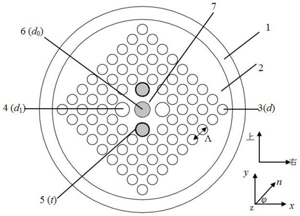
[0035] In the first embodiment, if figure 1 As shown, the two enlarged holes 4 that are symmetrical along the diagonal line are all metal-coated to form two coating holes 5, and the two coating holes 5 are filled with nematic liquid crystal E7, and the large hole toward the center of the fiber core Apply an external electric field to the nematic liquid crystals in 6 and two coating holes 5, and change the long axis direction n of the nematic liquid crystal molecules by adjusting the voltage of the applied electric field to realize the tuning of the filtering direction. The liquid crystal filling in the large hole 6 in the center of the fiber core can increase the asymmetry on the one hand, and more importantly, can realize the tuning of the filtering direction through the modulation of the external electric field.

[0036] In the present invention, due to filling the nematic liquid crystal E7 in the large hole 6 in the core area of ​​the fiber core, the arrangement of the nema...

Embodiment 2

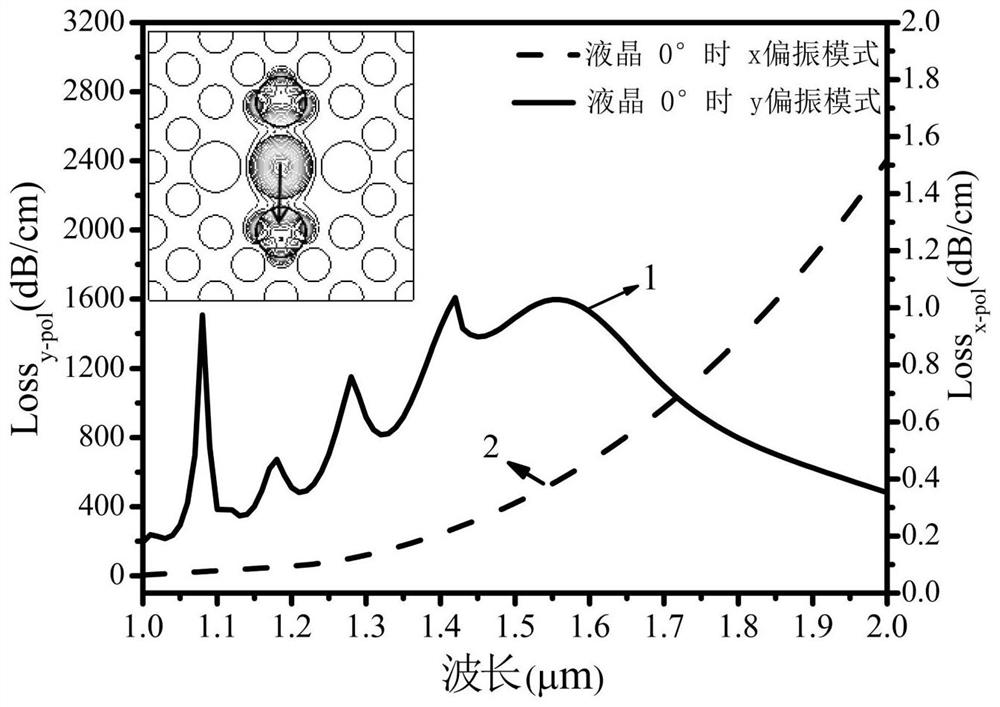
[0045] In the second embodiment, if Figure 6 As shown, the two enlarged holes that are symmetrical along the diagonal are all metal-coated to form two coating holes. Liquid crystal, only the large hole in the center of the optical fiber is filled with liquid crystal; Figure 7 As shown, the curves 1 and 2 are the rotation angles of the director direction n of the liquid crystal molecules respectively When 0° is the loss in the two orthogonal polarization directions of the fiber x and y. Depend on Figure 7 It can be seen that the curve 1 shows that although there is only one resonant coupling point between the core mode of the y-polarization direction between 1 μm and 2 μm, due to the incomplete coupling of the core mode and the surface plasmon mode in the y-polarization direction in the broadband band, the y-polarization The directional core mode loss is greater than 340dB / cm in the band 1μm and 2μm. Curve 2 shows the transmission loss of the core mode of the x-polarize...

Embodiment 3

[0047] The structure of the third embodiment is the same as that of the first embodiment, the difference is as Figure 8 As shown, in the inner cladding region, one of the four enlarged holes is arbitrarily selected for metal coating, and the coating hole is not filled with liquid crystals, and only the large hole in the center of the optical fiber is filled with liquid crystals. Such as Figure 9 As shown, the curves 1 and 2 are the rotation angles of the director direction n of the liquid crystal molecules respectively When 0° is the loss in the two orthogonal polarization directions of the fiber x and y. Depend on Figure 9 It can be seen that the curve 1 shows that the loss of the core mode in the y-polarization direction at the wavelength bands 1.05 μm and 2 μm is greater than 262 dB / cm. Curve 2 shows that the core mode loss in the x-polarization direction is less than 0.8dB / cm in the band between 1.05μm and 2μm. Compared with Embodiment 2, Embodiment 3 reduces a sym...


PUM

PropertyMeasurementUnit
diameteraaaaaaaaaa
thicknessaaaaaaaaaa
diameteraaaaaaaaaa

Abstract

The invention discloses a microstructure optical fiber broadband polarization filter with tunable filtering direction. The microstructure optical fiber includes a core area, an inner cladding area and an outer cladding air hole area. The substrate is composed of a large hole in the center of the fiber core filled with nematic liquid crystals, and the inner cladding area is composed of four enlarged holes, showing a C 4v Symmetrically distributed around the large hole in the center of the fiber core to form the first layer of air holes arranged in a square array. In the inner cladding area, metal coating is applied to any enlarged hole or two enlarged holes symmetrical along the diagonal to form The coating hole, the outer cladding air hole area includes three layers of square array of air holes, and the first layer of square array of air holes to form a completely symmetrical microstructure end structure in the horizontal and vertical directions; the nematic phase filled in the microstructured optical fiber The liquid crystal applies an external electric field, and the direction of the long axis of the nematic liquid crystal molecules is changed by adjusting the voltage of the external electric field, so as to realize the tuning of the filtering direction.

Description

technical field [0001] The invention relates to the technical field of optical fiber communication, in particular to a microstructure optical fiber broadband polarization filter with tunable filtering direction. Background technique [0002] With the rapid development of ultra-large bandwidth, high-speed, wide-bandwidth, and ultra-stable all-optical coherent optical fiber communication systems, the integration, miniaturization, and compaction of optical fiber devices have become one of the important trends in scientific and technological research and application. Microstructured optical fiber has a flexible and adjustable structure, and the free filling of selective functional materials makes it popular in optical fiber devices, and the use of functional materials to fill the core or cladding air holes of microstructured optical fibers can produce a ratio of pure Quartz material microstructured optical fiber has more transmission characteristics. At the same time, single po...

Claims


Application Information

Patent Timeline
Patent Type & Authority Patents(China)
IPC IPC(8): G02B6/02G02F1/13
CPCG02B6/02385G02F1/1326
Inventor 姜凌红王超张银铺
Owner 广州大鱼创福科技有限公司
Why Eureka
Try Eureka