High-precision controller for ultra-low-speed control moment gyroscope frame servo system

A technology for controlling torque gyroscopes and servo systems, applied in general control systems, control/regulation systems, adaptive control, etc., can solve the problems of reducing angular rate control accuracy and insufficient speed detection accuracy

Active Publication Date: 2021-05-28
BEIHANG UNIV
View PDF6 Cites 0 Cited by
  • Summary
  • Abstract
  • Description
  • Claims
  • Application Information

AI Technical Summary

Problems solved by technology

[0006] The technical problem to be solved by the present invention is: aiming at the problem of insufficient speed detection accuracy caused by the detection delay of the position sensor of the ultra-low speed frame servo system, thereby reducing the problem of its angular rate control accuracy, overcoming the deficiencies of the existing methods, by designing a state based on double sampling rate expansion The closed-loop estimation method of the observer realizes the accurate estimation of the instantaneous velocity and "lumped disturbance", and at the same time

Method used


Image

  • High-precision controller for ultra-low-speed control moment gyroscope frame servo system
  • High-precision controller for ultra-low-speed control moment gyroscope frame servo system
  • High-precision controller for ultra-low-speed control moment gyroscope frame servo system

Examples


specific Embodiment approach 1

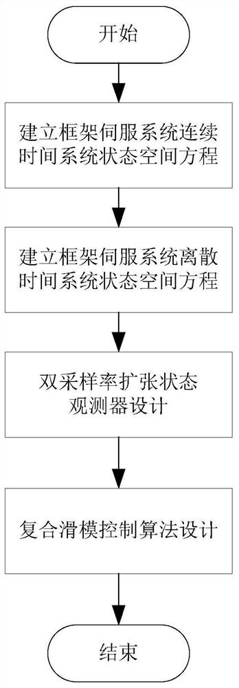
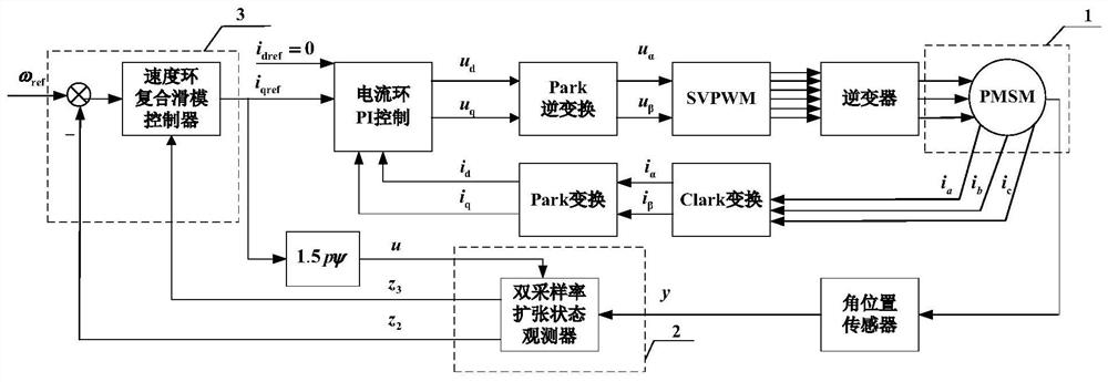
[0055] Specific implementation mode one: see figure 2 Describe this embodiment, a high-precision controller for an ultra-low-speed control moment gyro frame servo system described in this method, including a frame servo system mathematical model part 1, a double sampling rate expanded state observer part 2, and a composite sliding mode control algorithm part 3. The specific implementation steps are as follows:

[0056] Step 1: Build a mathematical model of the frame servo system:

[0057] According to the sampling period of the speed loop controller, the continuous-time system state-space equation of the frame servo system is discretized to obtain the discrete-time system state-space equation of the frame servo system, and the mathematical model part 1 of the frame servo system can be obtained.

[0058] (1) Establish the continuous time system state equation of the frame servo system as:

[0059]

[0060] where θ is the frame motor angular position, ω is the frame motor ...

specific Embodiment approach 2

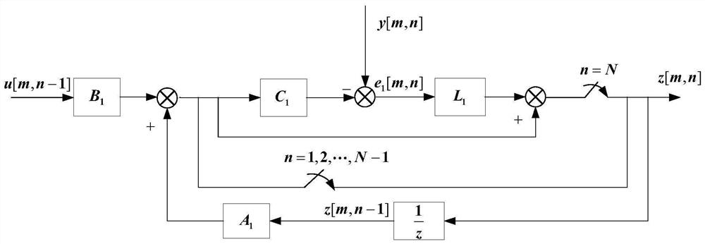
[0077] Embodiment 2: This embodiment is a further limitation of the high-precision controller of the ultra-low-speed control torque gyro frame servo system described in Embodiment 1. See image 3 Illustrate this embodiment, the specific design method of described double sampling rate expansion state observer part 2 is as follows:

[0078] The speed loop controller sampling time t=[m,n] between the position sensor data change time, where n=1,2,...,N-1, the position sensor cannot detect the angular position change of the frame motor, according to The state-space equations for a discrete-time system of frame motors estimate system states such as angular velocity and "lumped disturbances":

[0079]

[0080] Among them, the state variable estimation matrix z=[z 1 z 2 z 3 ] T the z 1 ,z 2 ,z 3 are used to estimate x 1 、x 2 、x 3 , […] T represents the transpose of the matrix […], z 1 [m,n] indicates that the sampling time of the speed loop controller is t=[m,n] when ...


PUM


Abstract

The invention provides a high-precision controller for an ultra-low-speed control moment gyroscope frame servo system. Firstly, a discrete time system state-space equation is obtained according to a continuous time system state-space equation of the ultra-low-speed frame servo system, then accurate estimation of instantaneous speed and lumped disturbance is achieved by designing a double-sampling-rate extended state observer, and finally, a composite sliding mode control algorithm is designed based on sliding mode control and disturbance compensation in a speed ring to suppress lumped disturbance. According to the high-precision controller for the ultra-low-speed control moment gyroscope frame servo system, provided by the invention, the double-sampling-rate extended state observer is designed to solve the problem that the estimation performance of an existing estimation method becomes poor under the influence of factors such as model parameter change of the ultra-low-speed frame servo system; the composite sliding mode control algorithm is further designed to enhance the disturbance suppression capability of the system; and starting from two aspects of sensing detection and disturbance suppression, the angular rate control precision of the ultra-low-speed frame servo system is comprehensively improved.

Description

technical field [0001] The invention belongs to the field of high-precision angular rate control of a magnetic suspension control torque gyro frame servo system, and specifically relates to a high-precision controller of an ultra-low speed control torque gyro frame servo system, which is used to improve the angular rate detection accuracy and interference suppression ability of the frame servo system. Realize the high-precision angular rate tracking control of the frame servo system, and then realize the high-precision torque output of the control torque gyro. Background technique [0002] The control torque gyro is forced to change the direction of the angular momentum vector of the high-speed rotor by the frame servo system to output the gyro torque. To ensure the accuracy of the output torque of the control torque gyro, it is necessary to realize the high precision control of the angular rate of the frame servo system. [0003] The frame servo system is composed of sensin...

Claims


Application Information

Patent Timeline
IPC IPC(8): G05B13/04
CPCG05B13/042
Inventor 李海涛王颖韩邦成史阳阳陈祥文
Owner BEIHANG UNIV
Why Eureka
Try Eureka