Jig

A jig and flexible display technology, which is applied in the field of jigs, can solve the problem that the edge of the flexible display module is easy to peel off, and achieve the effect of avoiding the peeling phenomenon

Pending Publication Date: 2021-05-28
CHENGDU BOE OPTOELECTRONICS TECH CO LTD +1
View PDF15 Cites 1 Cited by
  • Summary
  • Abstract
  • Description
  • Claims
  • Application Information

AI Technical Summary

Problems solved by technology

[0003] In order to solve the above technical problems, the present invention provides a jig to solve the problem that the edge of the flexible display module is easy to peel off

Method used


Image

  • Jig
  • Jig
  • Jig

Examples


Embodiment Construction

[0032] In order to make the purpose, technical solutions and advantages of the embodiments of the present invention more clear, the following will clearly and completely describe the technical solutions of the embodiments of the present invention in conjunction with the drawings of the embodiments of the present invention. Apparently, the described embodiments are some, not all, embodiments of the present invention. All other embodiments obtained by those skilled in the art based on the described embodiments of the present invention belong to the protection scope of the present invention.

[0033] In the description of the present invention, it should be noted that the terms "center", "upper", "lower", "left", "right", "vertical", "horizontal", "inner", "outer" etc. The indicated orientation or positional relationship is based on the orientation or positional relationship shown in the drawings, and is only for the convenience of describing the present invention and simplifying...


PUM


Abstract

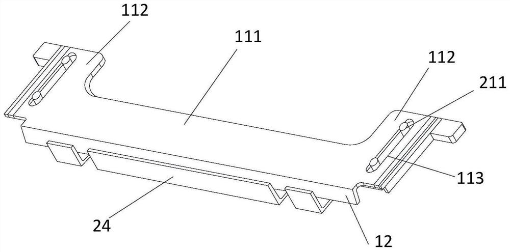
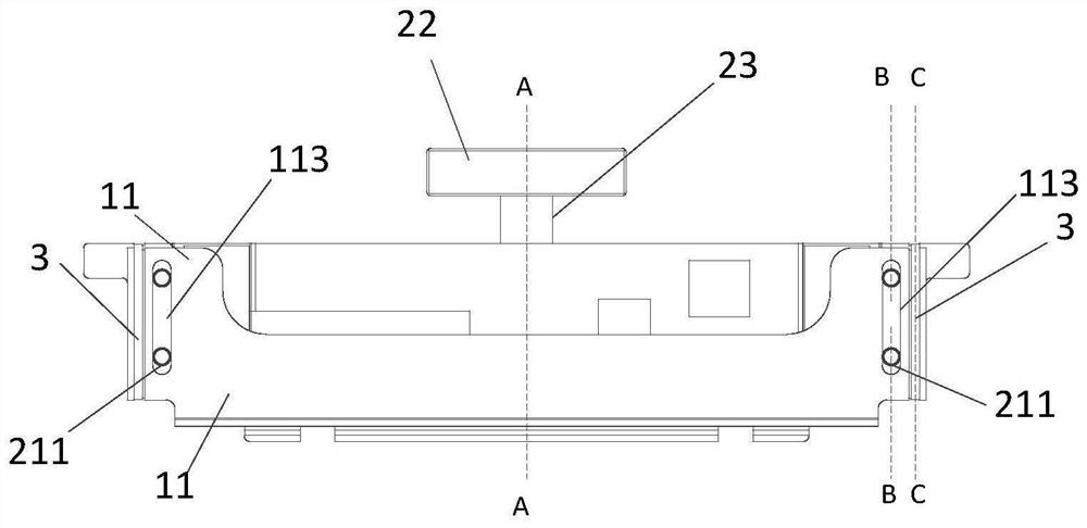
The invention relates to a jig which is used for avoiding stripping of a bending area of a flexible display module, the flexible display module comprises a non-bending area, the bending area and a binding area in the first direction, and the jig comprises a pressing structure and a limiting structure for limiting and fixing the pressing structure. The pressing structure is used for being arranged on the light emitting side of the flexible display module and comprises a pressing part used for being connected with the bending area in an abutting mode and a first connecting part connected with the limiting structure; and the limiting structure is used for being arranged on the backlight side of the flexible display module and comprises a second connecting part connected with the first connecting part in a matched mode.

Description

technical field [0001] The invention relates to the technical field of display product production, in particular to a jig. Background technique [0002] With the development of communication technology, movable display devices such as mobile phones and smart wearable devices are widely used. In order to ensure the portability of display devices, foldable and sliding display devices have become a trend. In order to have a beautiful and symmetrical appearance, the display module will design a curved Edge (edge) area. Due to the existence of rebound force, the adhesive layer with weak cohesive force will gradually separate after lamination, resulting in poor appearance and size. Customers At the same time, it will cause the bending (binding) area to be pulled, resulting in cracking (breakage) of the wiring in the bending area, resulting in poor display. Especially when the module is shipped and stored in the client warehouse, the possibility of stripping in the edge area is hi...

Claims


Application Information

Patent Timeline
IPC IPC(8): G09F9/30
CPCG09F9/301Y02E10/549
Inventor 王佳祥冯彬峰刘昌林新琦魏向东杨杰李飞
Owner CHENGDU BOE OPTOELECTRONICS TECH CO LTD
Why Eureka
Try Eureka