Power distribution cabinet and working method thereof

A power distribution cabinet and power technology, applied in substation/distribution device casing, electrical components, substation/switch layout details, etc., can solve the problems of electric shock, safety hazard, open fire, etc. , The effect of ensuring safety and reducing the probability of moisture

Pending Publication Date: 2021-05-28
梁彩霞
View PDF0 Cites 0 Cited by
  • Summary
  • Abstract
  • Description
  • Claims
  • Application Information

AI Technical Summary

Problems solved by technology

[0003] 1. The power distribution cabinet is generally in the shape of a cuboid box, and electrical components are installed on the back of the interior, so that if it is necessary to ensure heat dissipation, it is necessary to open larger and more cooling holes on the box, and the location of the opening There are also limitations. At the same time, when there are many and large cooling holes, it will cause serious internal dust ingress, and it is very easy to be damp, which seriously affects the service life of internal components and wires in the power distribution cabinet. At the same time, the power distribution cabinet adopts front opening. Install it in the same way, so that when the power distribution cabinet is operated, it is easy to cause the danger of electric shock and it is not easy to disconnect, which has certain potential safety hazards;
[0004] 2. The inside of the power distribution cabinet adopts a circuit structure, so as the temperature rises and the service life of the internal components is affected, it will cause aging of the line after a long time, because the circuit inside the power distribution cabinet itself is complicated And there are many, so it is easy to cause contact short circuit in the circuit, and at the same time an open flame will be generated, it is easy to form a larger flame inside the box and cause a larger fire situation, although in this case the alarm will be disconnected However, the flame has not been effectively controlled, which is likely to cause greater danger and damage

Method used


Image

  • Power distribution cabinet and working method thereof
  • Power distribution cabinet and working method thereof
  • Power distribution cabinet and working method thereof

Examples


Embodiment Construction

[0025] The following will clearly and completely describe the technical solutions in the embodiments of the present invention with reference to the accompanying drawings in the embodiments of the present invention. Obviously, the described embodiments are only some, not all, embodiments of the present invention. Based on the embodiments of the present invention, all other embodiments obtained by persons of ordinary skill in the art without making creative efforts belong to the protection scope of the present invention.

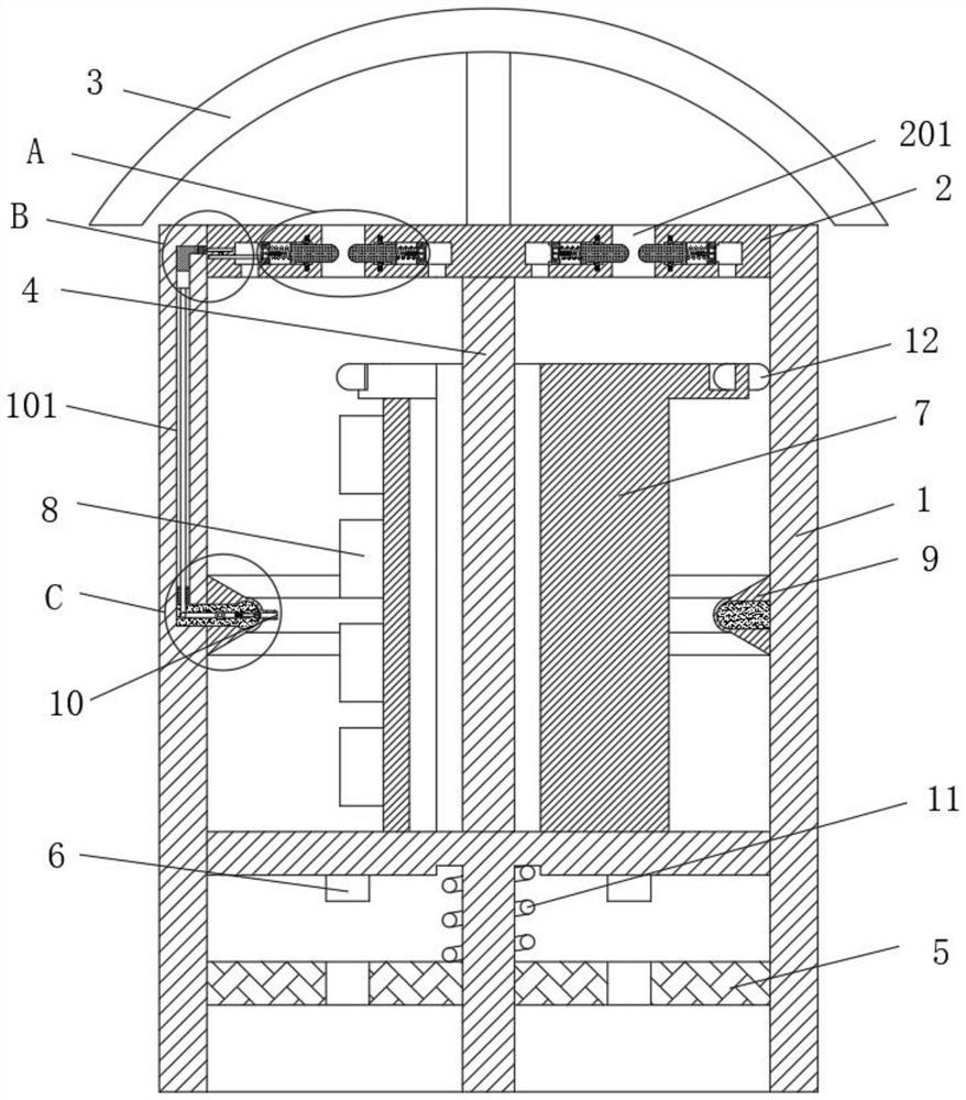
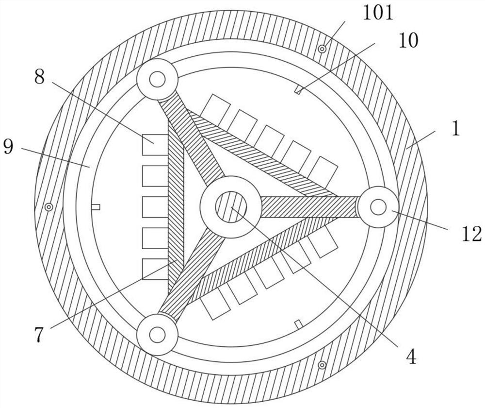
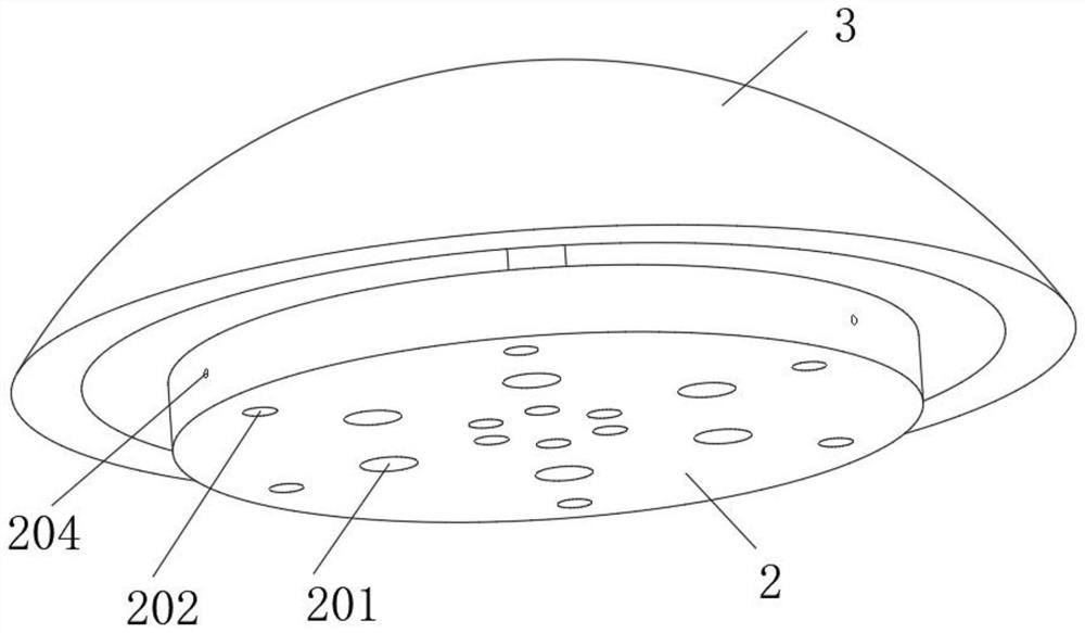
[0026] see Figure 1-6 , a power distribution cabinet, comprising a cabinet 1, the top of the cabinet 1 is screwed with a top cover 2, the top of the top cover 2 is fixedly connected with a top cover 3, and the top of the inner cavity of the cabinet 1 is located in the middle of the bottom plate. 4. The inner cavity of the cabinet 1 is located at the bottom of the bottom plate, and there is a floating plate 5 evenly opened with a slot. The bottom of the bottom...


PUM


Abstract

The invention relates to the technical field of power equipment, and discloses a power distribution cabinet which comprises a cabinet, the top of the cabinet is sleeved with a top cover in a threaded mode, the top of the top cover is fixedly connected with a top cover, a sleeve column is fixedly installed at the top, located in the middle of a bottom plate, of an inner cavity of the cabinet, the outer ring of the sleeve column is movably sleeved with a mounting frame, a powder storage ring is fixedly installed in the middle of an inner ring of the cabinet, nozzles are evenly installed on the inner side of the powder storage ring, vent holes are evenly formed in the middle ring of the top cover, air pressure holes are formed in the positions, located at the two sides of the vent holes, of the bottom of the top cover, movable grooves communicating with the vent holes and the air pressure holes are formed in the top cover, and transmission holes corresponding to the sleeve holes are formed in the side wall of the cabinet, the installation safety is improved by changing the structure of the whole power distribution cabinet. The mounting safety is improved by structural change of the whole power distribution cabinet, and air pressure change is used to control timely power failure and fire extinguishing in a fire to ensure the overall safety.

Description

technical field [0001] The invention relates to the technical field of power equipment, in particular to a power distribution cabinet and a working method thereof. Background technique [0002] The power distribution cabinet is the final equipment in the power system. It mainly realizes the distribution and control of circuits and electrical components. Its main structure is a box, and various electrical components can be installed inside it. The structure is simple and widely used. , but there are still some problems in the installation and use of the existing power distribution cabinets: [0003] 1. The power distribution cabinet is generally in the shape of a cuboid box, and electrical components are installed on the back of the interior, so that if it is necessary to ensure heat dissipation, it is necessary to open larger and more cooling holes on the box, and the location of the opening There are also limitations. At the same time, when there are many and large cooling...

Claims


Application Information

Patent Timeline
Patent Type & Authority Applications(China)
IPC IPC(8): H02B1/56H02B1/32H02B1/28H02B3/00
CPCH02B1/28H02B1/32H02B1/565H02B3/00
Inventor 不公告发明人
Owner 梁彩霞
Why Eureka
Try Eureka