Full-cycle suspension and torque compensation control method of bearingless switched reluctance motor

A technology of switched reluctance motor and control method, which is applied to AC motor control, control system, electrical components, etc., can solve the problems of frequent switching times of power switch tubes, large number of power converters, and increased control costs, etc. Control costs, reduce the number of use, and control the effect of simplicity

Active Publication Date: 2022-08-02
NANJING UNIV OF POSTS & TELECOMM
View PDF4 Cites 0 Cited by
  • Summary
  • Abstract
  • Description
  • Claims
  • Application Information

AI Technical Summary

Problems solved by technology

[0006] The purpose of the present invention is to overcome the deficiencies in the prior art, provide a full-cycle levitation and torque compensation control method for a bearingless switched reluctance motor, solve the existing levitation force control mechanism constraints, and need to control the current of each winding Independent control leads to a large number of power converters and high control costs. Current chopping control makes the switching times of the power switch tubes frequent and high switching losses, which increases the technical problems of control costs.

Method used


Image

  • Full-cycle suspension and torque compensation control method of bearingless switched reluctance motor
  • Full-cycle suspension and torque compensation control method of bearingless switched reluctance motor
  • Full-cycle suspension and torque compensation control method of bearingless switched reluctance motor

Examples


Embodiment Construction

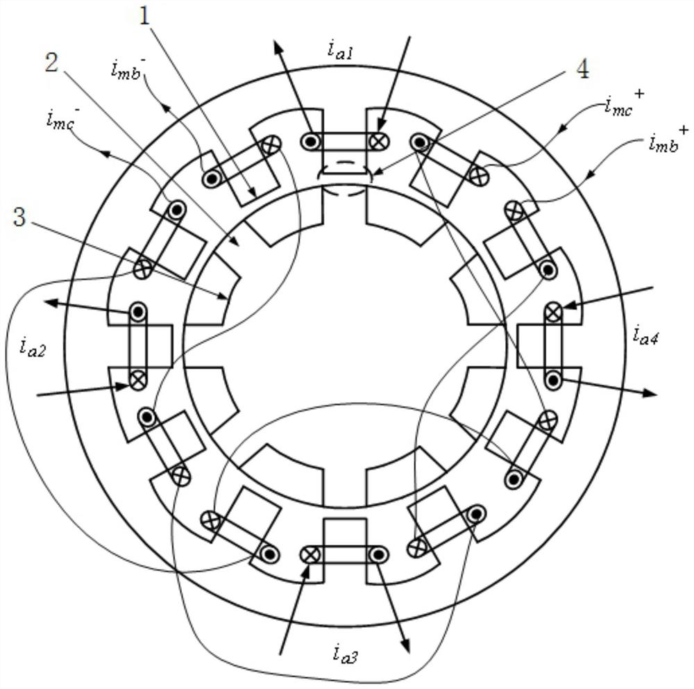
[0053] The control method provided by the embodiment of the present invention is suitable for a bearingless switched reluctance motor, as shown in FIG. 1 , which is a schematic structural diagram of a three-phase 12 / 8-pole composite rotor single-winding bearingless switched reluctance motor. 1 is the stator, 2 is the salient pole rotor, 3 is the cylindrical rotor, and 4 is the air gap. Stator 1 is a salient pole structure, the number of stator teeth is 12, and there is only one set of windings on each stator tooth; A-phase winding consists of 4 coils separated by 90°, and each winding is independently controlled; B-phase winding consists of 4 The 90° coils are formed in series; the remaining 4 X coils are connected in series to form the C-phase winding; the three-phase windings of A, B, and C are separated by 30° in space; the rotor is composed of a cylindrical rotor 3 and a salient-pole rotor 2, and the cylindrical rotor 3 It is a cylindrical structure, the salient pole rotor...


PUM


Abstract

The invention discloses a full-cycle suspension and torque compensation control method of a bearingless switched reluctance motor in the motor field, aiming at solving the limitation of the existing suspension force control mechanism, requiring independent control of the current of each winding, resulting in power The number of converters is required to be large, and the control cost is high. The current chopping control makes the switching frequency of the power switch tube frequent and the switching loss is high, which increases the technical problem of the control cost. The bearingless switched reluctance motor includes a stator and a rotor; the stator is a salient pole structure with a plurality of stator teeth, and each stator tooth is provided with a set of windings; A cylindrical rotor and a salient-pole rotor for generating torque and levitation force; the windings include A, B, and C three-phase windings, and the A-phase windings are separated by 90 in space. ° And it is composed of four windings that are independently controlled. The invention not only reduces the number of power switch tubes used and reduces the control cost, but also has simple control and convenient implementation.

Description

technical field [0001] The invention relates to a full-cycle suspension and torque compensation control method of a bearingless switched reluctance motor, belonging to the technical field of motors. Background technique [0002] Bearingless switched reluctance motor is a new type of magnetic levitation motor developed in the 1990s. Because the bearingless switched reluctance motor integrates the two functions of rotation and suspension, it can not only effectively solve the problems of loss and heat caused by bearingless friction during high-speed operation, but also further exert the high-speed adaptability of the switched reluctance motor, thereby strengthening the Its application basis in aerospace, flywheel energy storage, ships and other high-speed fields. [0003] With the continuous deepening of research, people gradually realize that whether the constraint between the effective output area between torque and suspension force can be solved, whether the two functions ...

Claims


Application Information

Patent Timeline
Patent Type & Authority Patents(China)
IPC IPC(8): H02P25/08
CPCH02P25/08
Inventor 刘泽远陈梅梁智蒋伟王振
Owner NANJING UNIV OF POSTS & TELECOMM
Why Eureka
Try Eureka