Plug valve sealing grinding machine

A grinding machine and cock valve technology, which is applied in the direction of grinding machine tools, grinding devices, metal processing equipment, etc., can solve the problems of unbalanced grinding force, affecting machining accuracy, and poor taper fit, etc., to achieve balanced grinding force and machining accuracy The effect of high and small adjustment range

Active Publication Date: 2021-06-01
浙江优机机械科技有限公司
View PDF8 Cites 3 Cited by
  • Summary
  • Abstract
  • Description
  • Claims
  • Application Information

AI Technical Summary

Problems solved by technology

[0002] Due to the processing error between the cock valve body and the plug body, that is, the taper between the valve body and the plug body is not so good, and there is a gap between the surfaces, which will leak when pressurized. In order to overcome this defect, Usually, the plug body is coated with abrasive material, and then the plug body is put into the valve body to make the valve body and the plug body grind each other to achieve good fit and smoothness. However, it is necessary to ensure the plug body and the valve body during the grinding process. The body is on the same vertical plane in height so that the plug body can enter the valve body for grinding, and avoid the phenomenon of seizure during grinding. In the existing technology, some grinding equipment adjusts the position of the valve body, but during the adjustment process It makes the technicians need to spend a lot of energy to adjust it; there is also a part of the equipment that connects the universal joint between the rotating shaft and the plug body to realize the position adjustment of the plug body, and there will be no misalignment between the valve body and the plug body. As a result, the plug body will be seized when it starts to grind, thus ensuring the normal operation of the equipment. However, due to the deflection of the universal joint during the working process, the grinding force of the plug body acting on the valve body will be unbalanced and affect the processing. precision

Method used


Image

  • Plug valve sealing grinding machine
  • Plug valve sealing grinding machine
  • Plug valve sealing grinding machine

Examples


Embodiment Construction

[0024]Next, the technical solutions in the embodiments of the present invention will be apparent from the embodiment of the present invention, and it is clearly described, and it is understood that the described embodiments are merely embodiments of the present invention, not all of the embodiments. Based on the embodiments of the present invention, there are all other embodiments obtained without making creative labor without making creative labor premises.

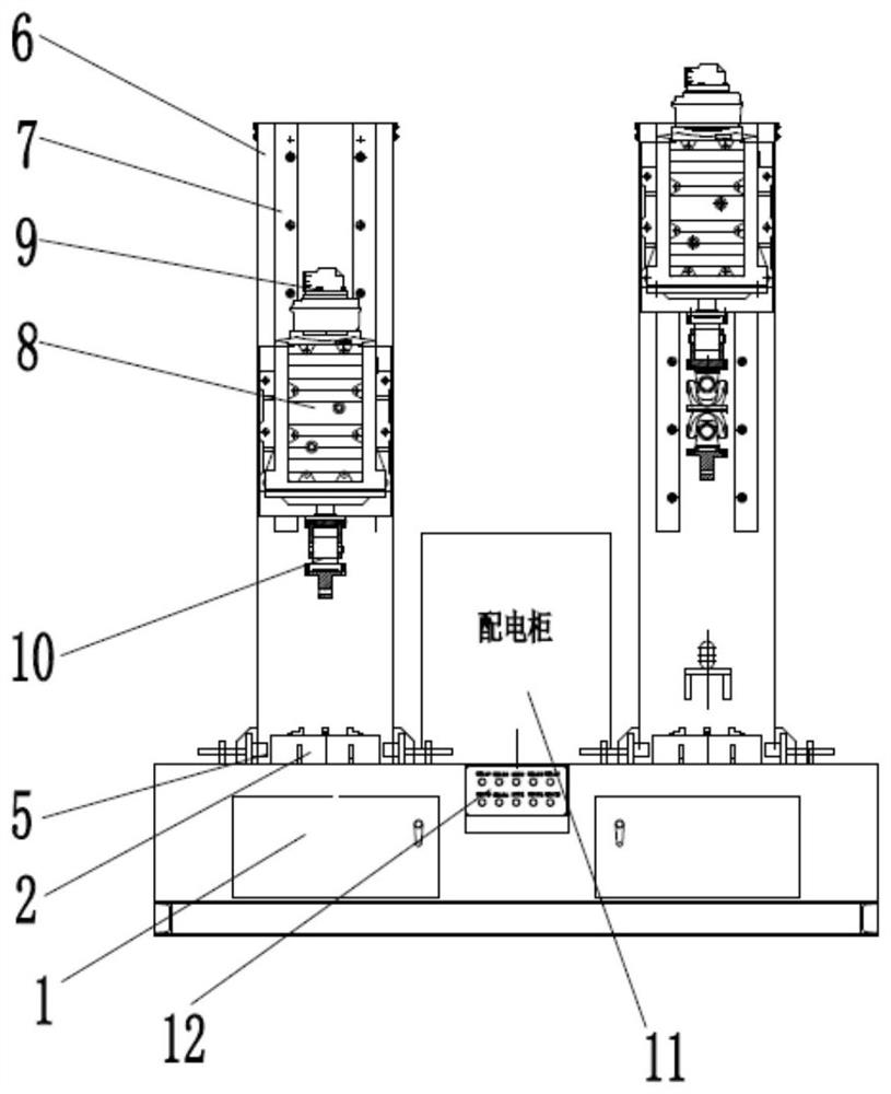
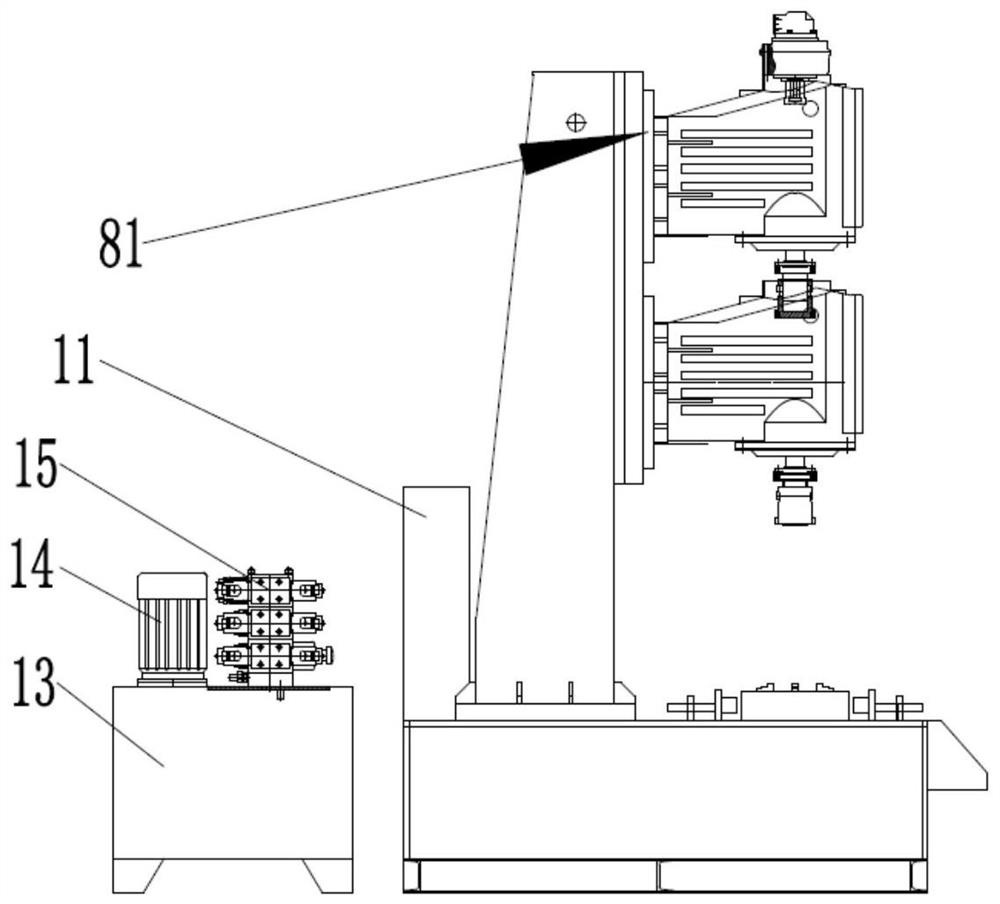
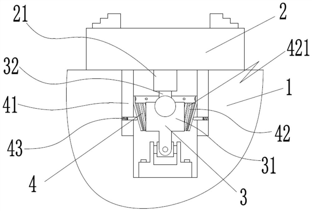
[0025]referenceFigure 1 to 5Further explanation of this application, such asfigure 1 withfigure 2 A plug valve sealing mill, including a table 1 having at least one column 6, and the back plate 87 of the gearbox 8 is slid in a sliding rail 7 located on the column 6, Further, the gearbox 8 is connected between the gearbox 8 between the gearbox 8 to be lively disposed on the column 6, and the table 1 is provided with a unit 3, placed in the The fixing holder 2 for the fixing valve seat is driven on the working table 1 and the unive...


PUM


Abstract

The invention discloses a plug valve sealing grinding machine which comprises a workbench, and at least one stand column is arranged on the workbench. The plug valve sealing grinding machine further comprises a gear box which is arranged on the stand column in a lifting manner, a universal mechanism which is arranged in the workbench, a fixed clamping base which is placed on the workbench and used for fixing a valve seat and a clamping mechanism which is arranged on the workbench and used for fixing the fixed clamping base, and an input shaft of the gear box is fixedly connected with a hydraulic motor; and a plug body is fixedly connected with an output shaft of the gear box through a telescopic mechanism, wherein the universal mechanism comprises a universal joint and a guide rod, one end of the universal joint is fixedly connected with the bottom of a containing hole located in the workbench, the guide rod is connected to the other end of the universal joint through a knuckle bearing, and the guide rod is connected with a guide sleeve of the fixed clamping base in a sliding fit manner. In the working process of the plug valve sealing grinding machine, the phenomena of meshing and jamming are avoided, a valve body and the plug body are stressed in a balanced manner, and the machining precision is high.

Description

Technical field[0001]The present invention relates to the field of valve body grinding techniques, and more particularly to a plug valve sealing mill.Background technique[0002]Since there is a machining error between the plug valve body and the plug, the taper match between the valve body, the plug is not as good, and there is a gap between the surface and the surface, and it will leak in the pressurization, in order to overcome this defect. It is usually applied to the abrasive material on the plug body, and then put the plug body into the valve body to mutter between the valve body and the plug body to achieve a good anastomosis, finish, but the grinding process is required to ensure the plug body and valve The body is at the same vertical surface in the same vertical surface so that the plug can enter the valve body for grinding, and avoiding the phenomenon of bitten death, in the conventional technique, partial grinding device is adjusted to the valve body position, but during a...

Claims


Application Information

Patent Timeline
Patent Type & Authority Applications(China)
IPC IPC(8): B24B37/00B24B37/34
CPCB24B37/00B24B37/34
Inventor 李珍武李珍贤
Owner 浙江优机机械科技有限公司
Why Eureka
Try Eureka