
Clamp

A technology of fixtures and clamping parts, which is applied in the field of electronic device testing, and can solve problems such as the inability to guarantee the accuracy of isolator electrical performance indicators

Pending Publication Date: 2021-06-01
无锡市高宇晟新材料科技有限公司
View PDF0 Cites 0 Cited by
  • Summary
  • Abstract
  • Description
  • Claims
  • Application Information

AI Technical Summary

Problems solved by technology

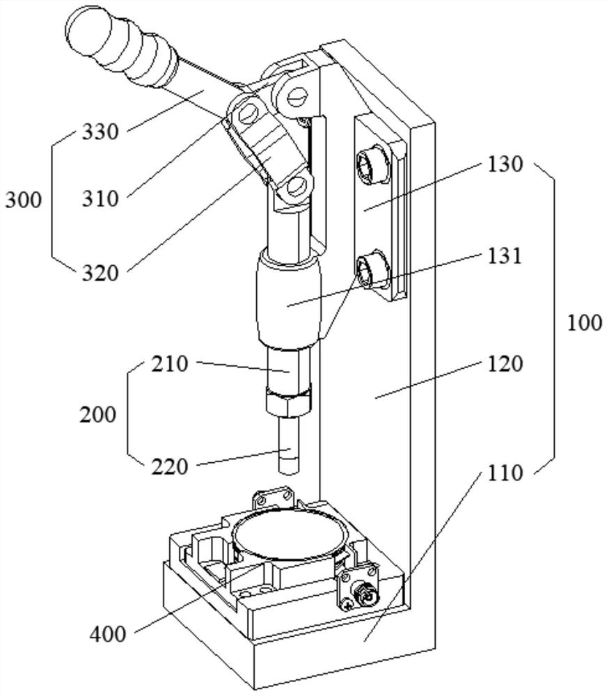
[0004] The purpose of the present invention is to provide a fixture to alleviate the technical problem in the prior art that manually pressing the isolator and the test frame cannot guarantee the accuracy of the measured electrical performance index of the isolator

Method used


Image

  • Clamp
  • Clamp
  • Clamp

Examples


Embodiment Construction

[0041] The technical solutions of the present invention will be clearly and completely described below in conjunction with the accompanying drawings. Apparently, the described embodiments are some of the embodiments of the present invention, but not all of them. Based on the embodiments of the present invention, all other embodiments obtained by persons of ordinary skill in the art without making creative efforts belong to the protection scope of the present invention.

[0042] In the description of the present invention, it should be noted that the terms "center", "upper", "lower", "left", "right", "vertical", "horizontal", "inner", "outer" etc. The indicated orientation or positional relationship is based on the orientation or positional relationship shown in the drawings, and is only for the convenience of describing the present invention and simplifying the description, rather than indicating or implying that the referred device or element must have a specific orientation, ...


PUM


Abstract

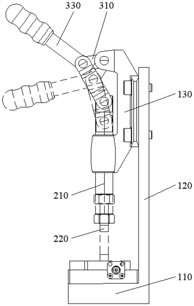
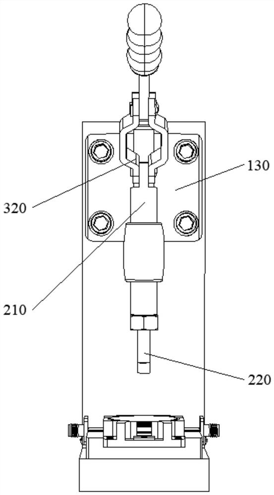
The invention provides a clamp, and relates to the technical field of electronic device testing. The clamp comprises a rack, a pressing part and a driving assembly. The pressing part is in sliding connection with the rack; and the driving assembly comprises a first connecting piece and a second connecting piece, the first connecting piece and the second connecting piece are hinged to form a first hinge point, and meanwhile the two ends of the first connecting piece and the two ends of the second connecting piece are hinged to the rack and the pressing part to form a second hinge point and a third hinge point respectively. The first hinge point, the second hinge point and the third hinge point have a collinear state and a non-collinear state under the action of external force, and the three points can drive the pressing part to do linear motion so as to press or loosen a piece to be clamped in the switching process of the two states. Through the clamp, the technical problem that the accuracy of the electrical performance index of an isolator cannot be ensured by manually pressing the isolator and a test frame in the prior art is solved, and the effect of improving the debugging efficiency and the accuracy of the electrical performance index is achieved.

Description

technical field [0001] The invention relates to the technical field of electronic device testing, in particular to a fixture. Background technique [0002] When testing the isolator, it is necessary to connect the test frame with SMA connector (SubMiniature version A, SMA interface) to the vector network analyzer, and then fit the isolator and the test frame tightly to ensure that the pins of the isolator are in contact with the test frame. The substrate contact of the test frame is good. According to the above, the accurate electrical performance index of the isolator can be displayed on the vector network analyzer. [0003] However, at present, the bonding between the isolator and the test frame mainly relies on manual compression, which cannot ensure that the pins of the isolator are in good contact with the substrate of the test frame, and thus cannot guarantee the accuracy of the electrical performance indicators of the isolator measured thereby; In addition, the manu...

Claims


Application Information

Patent Timeline
IPC IPC(8): B25B11/00
CPCB25B11/00
Inventor 宋培黄庆焕徐海新叶荣顾国治
Owner 无锡市高宇晟新材料科技有限公司
Learn More