A high-efficiency glazing device for silicon carbide ceramics for a new material
A technology of silicon carbide ceramics and new materials, applied in ceramic molding machines, manufacturing tools, etc., can solve the problems of low work efficiency and labor consumption, and achieve the effect of saving labor.
- Summary
- Abstract
- Description
- Claims
- Application Information
AI Technical Summary
Problems solved by technology
Method used
Image
Examples
Embodiment 1
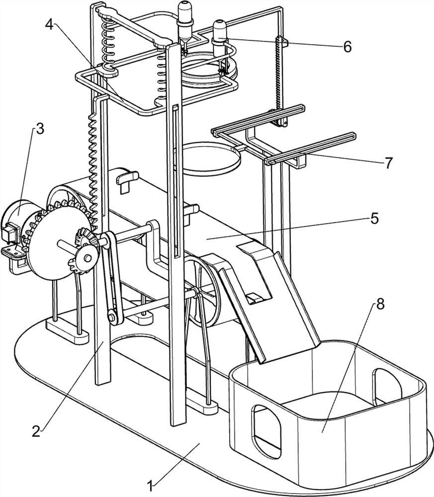
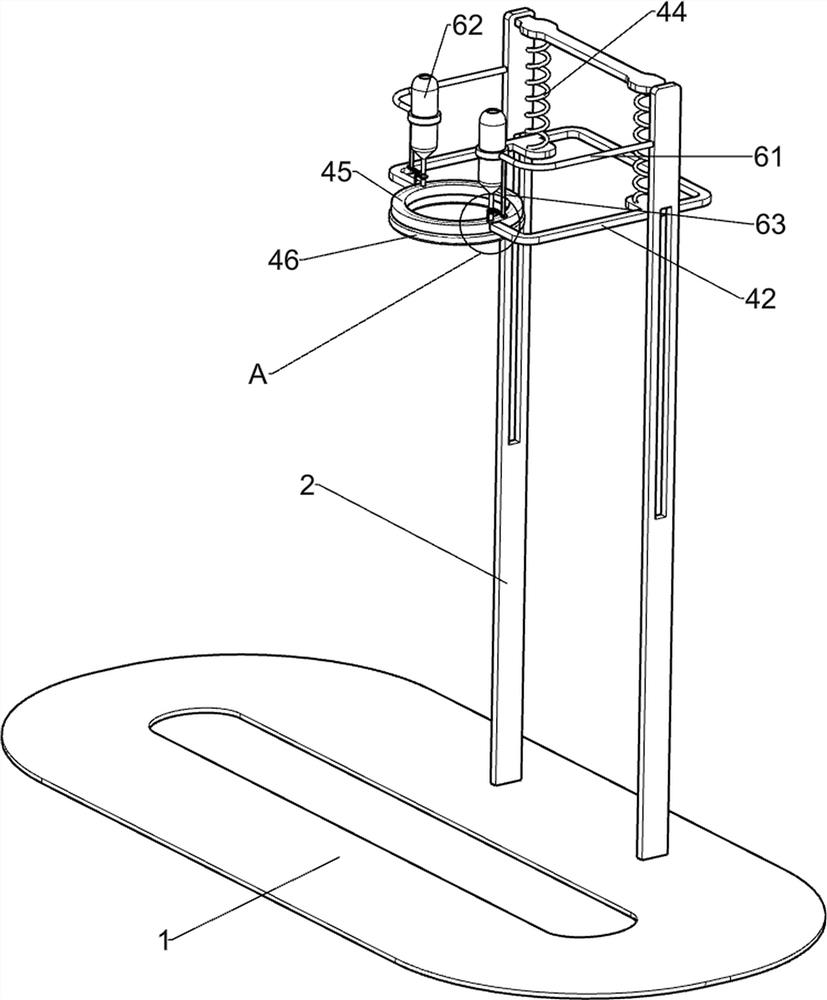
[0029] A high-efficiency glazing device for silicon carbide ceramics for new materials, such as Figure 1-3 As shown, it includes a bottom plate 1, a first guide carriage 2, a driving mechanism 3 and a lifting mechanism 4. A first guide carriage 2 is connected to the right side of the top of the bottom plate 1, and a driving mechanism 3 is provided on the first guide carriage 2. A lifting mechanism 4 is arranged between the driving mechanism 3 and the first guide carriage 2 , and the driving mechanism 3 and the lifting mechanism 4 are connected by transmission.
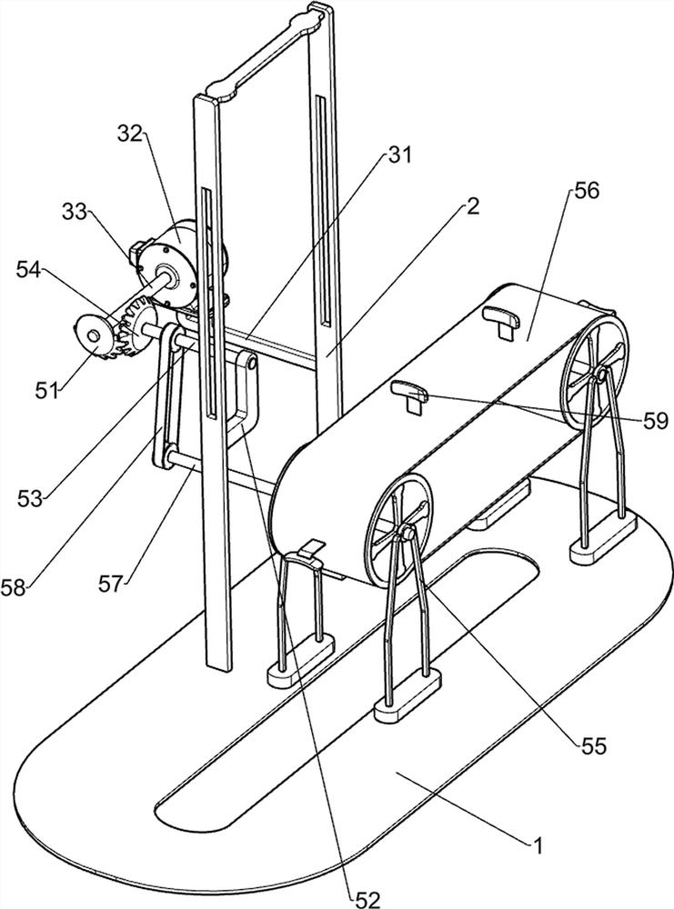
[0030] The driving mechanism 3 includes a first fixing frame 31, a low-speed motor 32 and a rotating shaft 33. A first fixing frame 31 is connected to the right side of the first guide frame 2, and a low-speed motor 32 is installed on the first fixing frame 31. A rotating shaft 33 is connected to the output shaft.
[0031] The lifting mechanism 4 includes a sector gear 41, a limit frame 42, a first rack 43, a first s...
Embodiment 2
[0034] On the basis of Example 1, as Figure 4 As shown, it also includes a transmission mechanism 5, and the transmission mechanism 5 includes a fan-shaped bevel gear 51, a second fixing frame 52, a first connecting shaft 53, a transmission bevel gear 54, a supporting frame 55, a belt transmission group 56, and a second connecting shaft. 57. The flat belt 58 and the stopper 59, the rotating shaft 33 is connected with the sector bevel gear 51, the first guide carriage 2 is connected with the second fixing frame 52, and the second fixing frame 52 is rotatably connected with the first connecting shaft 53 , the first connecting shaft 53 is connected with a transmission bevel gear 54, the sector bevel gear 51 will mesh with the transmission bevel gear 54, the top of the bottom plate 1 is connected with two support frames 55, and a belt transmission group is wound between the upper parts of the two support frames 55 56. A second connecting shaft 57 is connected to one of the transm...
Embodiment 3
[0039] On the basis of Example 2, as image 3 and Figure 7 As shown, it also includes a material blocking mechanism 7, and the material blocking mechanism 7 includes a second rack 71, a second guide carriage 72, a glaze receiving box 73, a third rack 74 and a spur gear 75. A second rack 71 is connected, a second guide carriage 72 is connected to the top left side of the bottom plate 1, a glaze receiving box 73 is slidably connected to the second guide carriage 72, and a third rack 74 is connected to the glaze receiving box 73 , a spur gear 75 is rotatably connected to the second guide carriage 72 , and the spur gear 75 meshes with the second rack 71 and the third rack 74 respectively.
[0040] For example, when there is a lot of glaze liquid in the glaze brushing foam 46, the excess glaze liquid will drip into the glaze receiving box 73, and the limit frame 42 drives the second rack 71 to move downward when the second rack 42 moves downward. After the rack 71 moves down to ...
PUM
 Abstract
Description
Claims
Application Information
 - R&D
- Intellectual Property
- Life Sciences
- Materials
- Tech Scout
- Unparalleled Data Quality
- Higher Quality Content
- 60% Fewer Hallucinations
Browse by: Latest US Patents, China's latest patents, Technical Efficacy Thesaurus, Application Domain, Technology Topic, Popular Technical Reports.
© 2025 PatSnap. All rights reserved.Legal|Privacy policy|Modern Slavery Act Transparency Statement|Sitemap|About US| Contact US: help@patsnap.com


