3D printing head feeding device

A feeding device and 3D printing technology, applied in coating devices, liquid material additive processing, processing and manufacturing, etc., can solve the problem of increasing the degree of sluggishness, affecting the efficiency of printing operations, the degree of feeding safety protection, aerodynamics and Hydraulic decline and other problems, to ensure the improvement of solidification, improve the effect of rack linkage operation, and improve the effect of refined processing

Pending Publication Date: 2021-06-01
LIAONING JIDIAN POLYTECHNIC
View PDF5 Cites 0 Cited by
  • Summary
  • Abstract
  • Description
  • Claims
  • Application Information

AI Technical Summary

Problems solved by technology

[0004] Aiming at the deficiencies of the existing technology, the purpose of the present invention is to provide a 3D printing nozzle feeding device to solve the liquid-cooled feeding of the printing nozzle and adapt to the thickening effect of the output end to form the thickening operation effect of the diluted fluid. , and the subsequent thickening amount is increasingly sticking to the flow channel and the output port, resulting in the impact of internal pressure expansion on the nozzle deformation of the clogged cylinder, resulting in a decrease in the aerodynamic and hydraulic performance of the internal pressure connection between the feed end and the discharge end, and the degree of sluggishness. High, thus affecting the overall printing operation efficiency and the problem of feeding safety protection

Method used


Image

  • 3D printing head feeding device
  • 3D printing head feeding device
  • 3D printing head feeding device

Examples


Embodiment 1

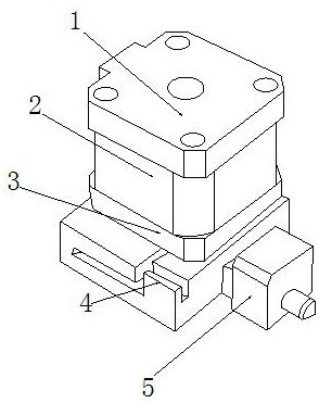
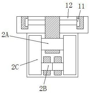
[0035] see Figure 1-Figure 8 , the present invention provides a 3D printing nozzle feeding device, its structure includes: end cover deck 1, roller rod double channel valve block 2, reverse buckle lining plate 3, guide shoe base plate 4, nozzle valve cap 5, the The roller rod double-channel valve block 2 is inserted under the bottom of the end cover deck 1 and is perpendicular to each other. Closely attached to the bottom surface of the reverse buckle liner 3 and on the same level, the nozzle valve cap 5 is inserted on the right side of the guide shoe base plate 4 and on the same level, the roller rod double channel valve block 2 A funnel column conduit 2A, a short ball valve tube 2B, and a gear sleeve roller rod 2C are provided. Two short ball valve tubes 2B are respectively inserted in the left and right lower corners of the funnel column conduit 2A. The roller rods 2C are mechanically connected and parallel to each other. The funnel column conduit 2A and the gear sleeve r...

Embodiment 2

[0043] see Figure 1-Figure 8 , the present invention provides a 3D printing nozzle feeding device, other aspects are the same as embodiment 1, the difference is:

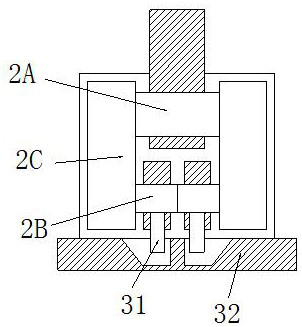
[0044] see image 3 , the reverse buckle lining 3 is composed of a reverse buckle rod 31 and a horizontal lining 32. The reverse buckle rod 31 is installed inside the horizontal lining 32. Together and perpendicular to each other, the effect of pulling and installing the shell is formed on the top of the horizontal liner 32 through the buckle bar 31 .

[0045] see Figure 6 , the anti-button bar 31 is made up of an alveolar pole 311 and a trapezoidal pinch plate 312. The alveolar pole 311 is installed on the top of the trapezoidal pinch plate 312. Inserted together and on the same vertical plane, the alveolar pole 311 is a composite pole structure with rack grooves on the left and right, which is convenient for the bolt to form a reverse buckle and draw and the shell plate connected by the top lock pin to closel...


PUM


Abstract

The invention discloses a 3D printing head feeding device. The 3D printing head feeding device structurally comprises an end cover deck, a roller rod double-way valve block, a left-hand screw lining plate, a guide shoe base plate and a printing head valve bonnet. According to the 3D printing head feeding device, with the cooperation of the end cover deck and the roller rod double-way valve block, a material is guided at the top part of a double pipe through a funnel column guide pipe to adapt to rolling, butting and pressure adjustment operations of gear sleeve roller rods to form a through linked rotary pressure adjustment and converging operation, and accordingly, the effect of rolling and thickening operations of ball valve spools when cover plate blocks make the funnel column guide pipe turned on for feeding, converging and continuous feeding for a printing head is improved, the improvement of the printing molding solidification degree and the efficient butting adjustment of a valve block at the anti-pressurization feeding end of the printing head are guaranteed, and the effect of a frame linked operation of a safety explosion-proof cylinder and the fluency of cyclone slow-release anti-adhesive feeding of the printing head are promoted, thereby improving the overall fine processing effect of feeding of the printing head.

Description

technical field [0001] The invention is a 3D printing nozzle feeding device, which belongs to the field of printing. Background technique [0002] The 3D printing of the printer is adapted to the overall elevation imaging to form the printing density and fineness of the base point scanning and the overall shaping scanning, so as to ensure the stability of the molding of the feeding and discharging materials of the nozzle and the fit of the printing, so as to ensure the continuity of subsequent printing and Fluency, the shortcomings of the current technology to be optimized are: [0003] The liquid cooling feed of the printing nozzle needs to adapt to the viscous plastic effect of the output end to form the thickening operation effect of the diluted fluid, and the subsequent thickening amount will increasingly stick to the flow channel and the output port, causing the internal pressure of the nozzle to block and explode. Due to the influence of expansion, the aerodynamic and...

Claims


Application Information

Patent Timeline
Patent Type & Authority Applications(China)
IPC IPC(8): B29C64/106B29C64/209B29C64/20B33Y30/00
CPCB29C64/106B29C64/209B29C64/20B33Y30/00
Inventor 张超
Owner LIAONING JIDIAN POLYTECHNIC
Why Eureka
Try Eureka