Automobile door tensioning device and automobile door body comprising same
What is AI technical title?
AI technical title is built by Patsnap AI team. It summarizes the technical point description of the patent document.
A technology of tensioning device and car door, which is applied in the field of automobile door body and car door tensioning device
Pending Publication Date: 2021-06-01
QINGDAO TIANCHENJIACHUANG AUTO PARTS CO LTD
View PDF0 Cites 2 Cited by
Summary
Abstract
Description
Claims
Application Information
AI Technical Summary
This helps you quickly interpret patents by identifying the three key elements:
Problems solved by technology
Method used
Benefits of technology
Problems solved by technology
This also indirectly limits the installation position of the control components and the lock inside the door body, and limits the shape and size of the lock.
Method used
Image
Click on the blue label to locate the original text in one second.
Reading with bidirectional positioning of images and text.
Examples
Embodiment 1
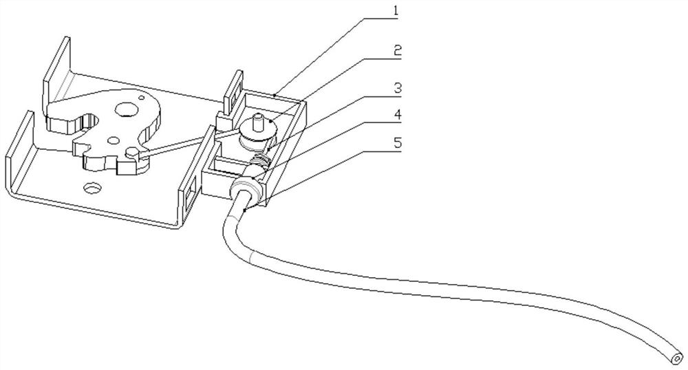
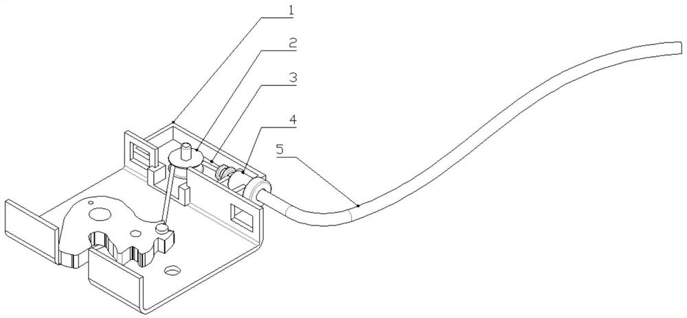
[0036] Such as figure 1 As shown, a car door tensioning device includes a pull cable 3, a lock tongue and a guide 2 arranged in the housing 1, one end of the pull cable 3 is connected with the lock tongue, and the pull cable 3 cooperates with The guide 2 changes direction, and the other end of the cable 3 passes through the guide 2 and extends out of the housing 1 .
[0037] The cable 3 is led out from the housing 1, and the transmission direction of the cable 3 is changed through the guide 2, and the two ends of the cable 3 are located on the same side of the guide 2. The car door tensioning device of the present invention can be applied to locks of various shapes because the direction of the drag cable 3 can be changed. In the car door tensioning device in the prior art, in order to make the pull cable 3 reach the optimal pulling angle, that is, the most effective and labor-saving when pulling the deadbolt, the angle at which the pull cable 3 is pulled out from the lock is ...
Embodiment 2
[0046] On the basis of Embodiment 1, the guide 2 is replaced with a fixed pulley block. The position of the fixed pulley is flexibly set according to the shape of the car lock or the inner space of the car door body, and the transmission angle of the drag cable 3 is changed.
Embodiment 3
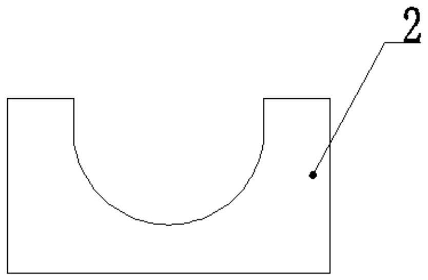
[0048]On the basis of Embodiment 1, the guide member 2 is replaced with a guide groove with a direction change, and the pulling cable 3 is placed in the guide groove to change the extending direction.
[0049] The specific shape of the guide groove is a groove or a pipe with a bending or bending angle in the length direction. The drag cable 3 moves in the guide groove, and the guide groove can be set at various bending angles as required, so as to flexibly control the moving direction of the drag cable 3 .
[0050] As a further improvement of this embodiment, the cross section of the guide groove is circular or semicircular. The sliding friction of the drag cable 3 in the guide groove is small, which reduces the abrasion between the drag cable 3 and the guide groove.
[0051] During use, the lockset of the car door lock is connected with the control part by a drag cable 3, and one end of the drag cable 3 is connected to the rear side of the dead bolt in the lockset housing, a...
PUM
Abstract
The invention relates to an automobile door tensioning device and an automobile door body comprising the same. The automobile door tensioning device comprises an inhaul cable, a spring bolt and a guide part, wherein the spring bolt and the guide part are arranged in a shell, one end of the inhaul cable is connected with the spring bolt, the inhaul cable is matched with the guide part to change directions, and the other end of the inhaul cable penetrates through the guide part and extends out of the shell. The automobile door body provided by the invention comprises the automobile door tensioning device. Due to the fact that the direction of the inhaul cable can be changed, the automobile door tensioning device can be suitable for locks of various shapes. The installation position of a control part in the automobile door body is flexible and is not affected by the angle of the inhaul cable. The automobile door tensioning device can be applied to the automobile door body with a narrow internal space.
Description
technical field [0001] The invention relates to the field of motor vehicle door locks, in particular to a vehicle door tensioning device and a vehicle door body comprising the same. Background technique [0002] Along with the rapid development of the motor vehicle industry, a car door tensioning device has been arranged in the door lock of a part of the motor vehicle. When the car door is not closed tightly, the car door tensioning device will automatically pull the car door tightly to lock the car door. [0003] The car door tensioning device includes a control part and a lockset connected by a drag cable, the control part controls the drag cable to pull the dead bolt in the lockset to realize locking, and the drag cable is connected to a specific position of the dead bolt. In order to make the pull cable reach the optimal pulling angle, that is, the most effective and labor-saving when pulling the dead bolt, the angle at which the pull cable is drawn out of the lockset i...
Claims
Application Information
Patent Timeline
Application Date:The date an application was filed.
Publication Date:The date a patent or application was officially published.
First Publication Date:The earliest publication date of a patent with the same application number.
Issue Date:Publication date of the patent grant document.
PCT Entry Date:The Entry date of PCT National Phase.
Estimated Expiry Date:The statutory expiry date of a patent right according to the Patent Law, and it is the longest term of protection that the patent right can achieve without the termination of the patent right due to other reasons(Term extension factor has been taken into account ).
Invalid Date:Actual expiry date is based on effective date or publication date of legal transaction data of invalid patent.

