
Locking and fixing device facilitating submarine pipeline transportation

A technology for fixing devices and subsea pipelines, applied in the directions of pipes/pipe joints/fittings, sleeve/socket connections, through components, etc., can solve the problems of lack of availability, and achieve the effect of convenient transportation, rapid installation and disassembly, and convenient laying out.

Active Publication Date: 2021-06-01
福建省恒基建设股份有限公司 +7
View PDF15 Cites 0 Cited by
  • Summary
  • Abstract
  • Description
  • Claims
  • Application Information

AI Technical Summary

Problems solved by technology

However, this equipment does not have the ability to place the locking device on the inner wall of the pipeline when the submarine pipeline is laid to avoid seawater corrosion

Method used


Image

  • Locking and fixing device facilitating submarine pipeline transportation
  • Locking and fixing device facilitating submarine pipeline transportation
  • Locking and fixing device facilitating submarine pipeline transportation

Examples


specific Embodiment approach 1

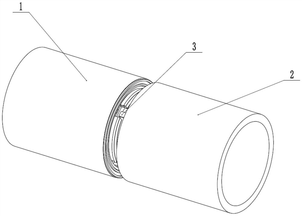
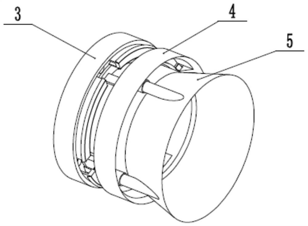
[0029] Such as Figure 1 to Figure 9 As shown, a locking and fixing device for submarine pipeline transportation is convenient, including an inner sealing pipe 1, an outer connecting pipe 2, an inner pipe fixing and connecting variable diameter seat 3, an outer pipe connecting variable diameter locking seat 4 and a variable diameter outer locking seat 5. The inner tube is fixedly connected to the variable diameter seat 3 and is fixedly connected to the outer end of the inner closed tube 1, the outer tube is connected to the variable diameter locking seat 4 and is fixedly connected to the inner end of the outer connecting tube 2, and the inner tube is fixedly connected to the variable diameter seat 3 and the outer tube connecting variable diameter locking seat 4 are in clearance fit with each other, and the variable diameter outer locking seat 5 is inserted into the outer tube connecting variable diameter locking seat 4, and the variable diameter outer locking seat 5 is fixedly ...

specific Embodiment approach 2

[0031] Such as Figure 1 to Figure 9 As shown, this embodiment further explains Embodiment 1. The outer wall of the inner closed pipe 1 is provided with a plurality of sealing grooves, and the inner wall of the outer connecting pipe 2 is provided with a plurality of sealing grooves. The inner sealing pipe 1 and the outer connecting pipe 2 are provided with a plurality of sealing rings. After locking the inner closed pipe 1 and the outer connecting pipe 2, multiple sealing rings are used to prevent leakage.

specific Embodiment approach 3

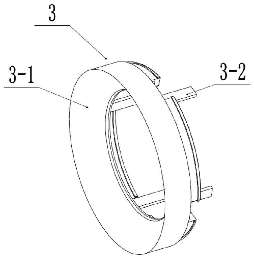
[0033] Such as Figure 1 to Figure 9 As shown, this embodiment will further explain the second embodiment. The inner tube fixedly connected with the variable diameter seat 3 includes the internal variable diameter seat 3-1, a plurality of clearance locking helical racks 3-2, and a locking ring Groove 3-3, multiple top-tight round hole grooves 3-4, multiple locking seats 3-5 and multiple locking slope grooves 3-6, the inner reducing seat 3-1 is fixedly connected to the inner wall of the inner closed tube 1 The outer end of the outer end, a plurality of gap locking helical racks 3-2 are uniformly fixedly connected to the rear end of the inner reducer 3-1, and the locking ring groove 3-3 is arranged at the rear end of the inner reducer 3-1 , a plurality of top tight round hole grooves 3-4 are evenly arranged in the locking ring groove 3-3, and a plurality of locking seats 3-5 are evenly fixedly connected in the locking ring groove 3-3, and the locking seat 3 The two ends of -5 a...


PUM


Abstract

The invention relates to the field of transportation pipelines, in particular to a locking and fixing device facilitating submarine pipeline transportation. The locking and fixing device comprises an inner closed pipe, an outer connecting pipe, an inner pipe fixed connection variable-diameter seat, an outer pipe connection variable-diameter locking seat and a variable-diameter outer locking seat, and the inner pipe fixed connection variable-diameter seat is fixedly connected with the outer end of the inner closed pipe; and the outer pipe connection variable-diameter locking seat is fixedly connected to the inner end of the outer connecting pipe, the inner pipe fixed connection variable-diameter seat and the outer pipe connection variable-diameter locking seat are in clearance fit, the variable-diameter outer locking seat is inserted into the outer pipe connection variable-diameter locking seat in a clearance mode, and the variable-diameter outer locking seat and the inner pipe fixed connection variable-diameter seat are meshed through a bevel gear. The locking and fixing device has the beneficial effects that the locking device is arranged in the pipeline, so that the external locking connecting device is prevented from being corroded by seawater after the pipeline is paved on the seabed.

Description

technical field [0001] The invention relates to the field of transportation pipelines, in particular to a locking and fixing device for convenient submarine pipeline transportation. Background technique [0002] Patent No. CN201921000426.1 discloses a pipeline locking mechanism and a synchronous rotation device for pipelines and rollers. The pipe locking mechanism is used to lock the first pipe and the second pipe, and includes a locking ferrule and a locking clip that cooperate with each other, and the locking ferrule is sleeved on the first pipe , the locking clip is arranged in the second pipe, the locking clip sequentially includes a first inclined section, an external thread section and an internal locking section, and the locking clip sequentially includes the first An outer locking section matched with an inclined section, an inner threaded section matched with said outer thread, and a second inclined section matched with said inner locking section. In the pipeline ...

Claims


Application Information

Patent Timeline
Patent Type & Authority Applications(China)
IPC IPC(8): F16L21/08
CPCF16L21/08
Inventor 杨凤茹
Owner 福建省恒基建设股份有限公司
Learn More