
Test tool structure capable of simulating load operation of motor
A technology for load operation and test tooling, applied in motor generator testing, environmental/reliability testing, measuring devices, etc., can solve the problems of inaccurate test results, inability to evaluate motor performance, and inability to simulate the working state of the motor, and achieve a comprehensive performance effect
- Summary
- Abstract
- Description
- Claims
- Application Information
AI Technical Summary
Problems solved by technology
Method used
Image

Examples
Embodiment
[0030] as attached figure 1 to attach Figure 8 Shown:
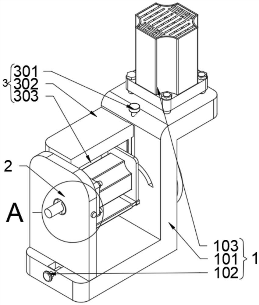
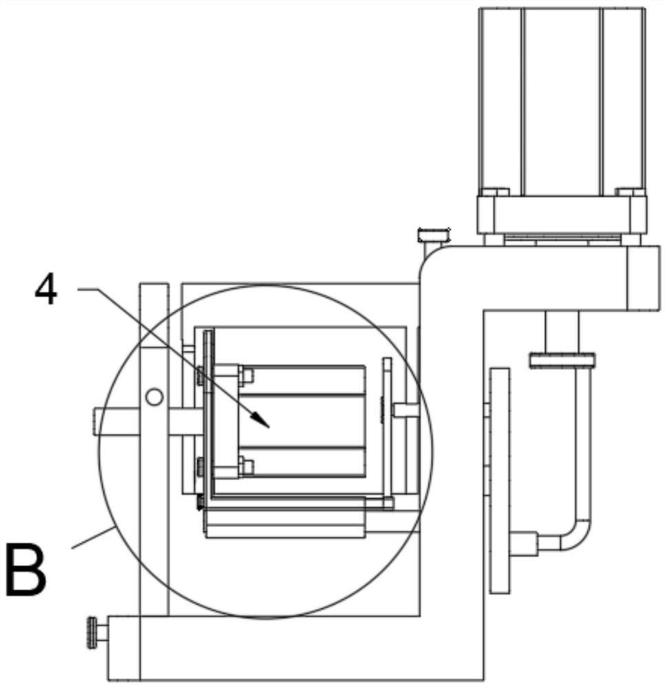
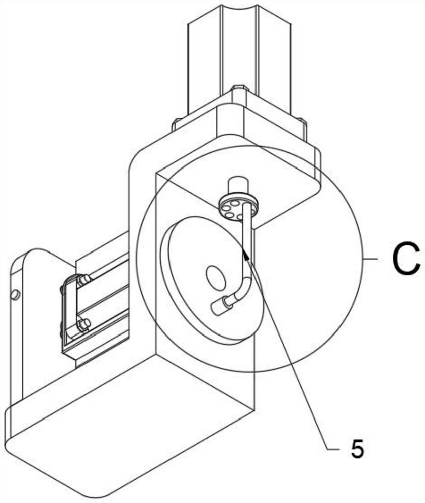
[0031] The present invention provides a test tooling structure capable of simulating the load operation of the motor, including: a limit mechanism 2, a simulation mechanism 3 and a swing mechanism 5, the limit mechanism 2 is slidably connected to the top position of the bearing mechanism 1; the simulation mechanism 3 Slidingly connected to the left side of the bearing mechanism 1; the swing mechanism 5 is transmission connected to the bottom end position of the bearing mechanism 1, and the left end of the swing mechanism 5 is also equipped with a drag mechanism 4; the swing mechanism 5 also includes a guide rod 503, a connecting rod Column 504 and oscillating plate 505, guide rod 503 is L-shaped structure design, and the insertion of guide rod 503 is in the bottom position of guide plate 502, and the right end surface of oscillating plate 505 is fixedly connected with connecting post 504, and the inside of connecting po...
PUM
 Abstract
Description
Claims
Application Information