[0024] The following will clearly and completely describe the technical solutions in the embodiments of the present invention with reference to the accompanying drawings in the embodiments of the present invention. Obviously, the described embodiments are only some, not all, embodiments of the present invention. Based on the embodiments of the present invention, all other embodiments obtained by persons of ordinary skill in the art without making creative efforts belong to the protection scope of the present invention.
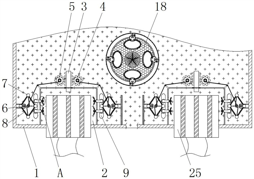
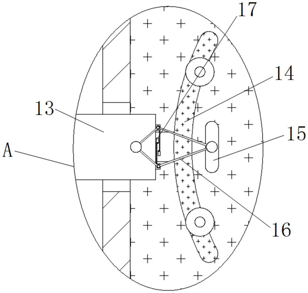
[0025] see Figure 1-5 , a switch that connects the network cable stably and prevents poor heat dissipation, including a housing 1, a cavity 2 is opened inside the housing 1, a rack bar 3 is slidably connected to the top of the cavity 2, and the left and right sides of the rack bar 3 A gear 4 is connected in rotation, and a winding group 5 is fixedly installed on the periphery of the gear 4. The winding group 5 is elastically connected to the winding rope sleeve 6 through the connecting wire, and the winding rope sleeve 6 is elastically connected to the sliding blocks 7 at the upper and lower ends through the connecting wire. The left and right sides of the inner cavity 2 of the housing 1 are rotatably connected with a rope wrap 6, and the inside of the housing 1 is slidably connected with a sliding block 7. The number of the sliding blocks 7 is the same as the number of the connecting rods 8, which is four, far away from the cavity. The sliding block 7 of 2 is fixedly connected to the inside of the housing 1 through a return spring, the proximal end of the sliding block 7 is movably connected with a connecting rod 8, and the end of the sliding block 7 close to the cavity 2 is fixedly connected with a fixed plate 9, and the front and rear of the fixed plate 9 The periphery of both ends is slidingly connected with a rotating rod 10, and the center of the rotating rod 10 is connected with a rotating pin 11. One end of the rotating rod 10 close to the rope winding sleeve 6 is fixedly installed with a speed limiting block 12, and the end of the fixed plate 9 near the cavity 2 is fixedly installed. There is a fixed block 13, the end of the fixed block 13 close to the cavity 2 is fixedly installed with a limit block 14, and the end of the fixed block 13 close to the cavity 2 is slidably connected with a push block 15, and the push block 15 is located at the end of the limit block 14 close to the cavity 2 At one end, the end of the push block 15 close to the fixed block 13 is rotatably connected with a connecting rod 16, and the near end of the connecting rod 16 is fixedly connected with a contact 17, and the contact 17 is electrically connected with the transmission end of the rotating pin 11. A dust removal disc 18 is fixedly installed on the top, and a power supply 19 is fixedly installed in the center of the dust removal disc 18. The center of the dust removal disc 18 is rotatably connected with a guide rod 20. The outer periphery of the dust removal disc 18 is equipped with a rubber block 21. A collection chamber 22 is fixedly installed, and a guide plate 23 is fixedly installed on the end of the collection chamber 22 close to the edge of the dust removal disc 18. The surface of the guide plate 23 is provided with a through hole, and the edge of the dust removal disc 18 is rotatably connected with a negative pressure fan 24. 24 is rotationally connected with the edge of the dust removal disc 18 through the transmission rod, the transmission rod is connected with a motor, and the inside of the cavity 2 is slidably connected with a crystal head 25 .
[0026] Working principle: insert the crystal head 25 into the cavity 2, the top of the crystal head 25 contacts the gear bar 3 and drives the gear bar 3 to move upwards, the gear bar 3 drives the gear 4 to rotate during the movement, and the gear 4 rotates to drive the winding group 5 rotates, and the winding group 5 rotates to drive the winding rope sleeve 6 to rotate through the connecting wire, the winding rope sleeve 6 rotates and pulls the sliding block 7, and the sliding block 7 is pulled by the connecting rod 8 to drive the fixed plate 9 to move towards the direction of the cavity 2, and the fixed The movement of the plate 9 drives the stop block 14 to move towards the cavity 2, so that the stop block 14 fixes the crystal head 25, and at the same time, the push block 15 is driven by the force of the crystal head 25 to drive the connecting rod 16 to rotate, thereby making the contact 17 contact , contact 17 makes the driving end of rotating pin 11 energized, rotating pin 11 begins to rotate to drive rotating rod 10 to rotate, rotating rod 10 rotates to drive speed limiting block 12 to move to the direction of winding rope cover 6, so that winding rope covering 6 stops rotating, Prevent continuing to increase the fixing strength of the crystal head 25 and cause the crystal head 25 to be damaged, turn on the power supply 19, the power supply 19 makes the guide rod 20 energized, the drive guide rod 20 rotates, the guide rod 20 rotates and rubs with the rubber block 21, in the electric field Under the action, the negative charge moves to the electrified guide rod 20, so that the two ends of the electrified guide rod 20 have different charges, and then an electrostatic field is generated on the surface of the electrified guide rod 20, and the dust is adsorbed under the action of static electricity. At this time, the motor is turned on , the motor drives the transmission rod connected to the transmission to rotate, and the transmission rod drives the negative pressure fan 24 to rotate, and the negative pressure fan 24 rotates to absorb the dust in the electrostatic field, so that the dust is adsorbed into the inside of the collection chamber 22, preventing the dust from accumulating and causing the heat dissipation of the exchanger equipment reduction in effect.
[0027] To sum up, the connection cable is stable and prevents poor heat dissipation. By inserting the crystal head 25 into the cavity 2, the top of the crystal head 25 contacts the rack bar 3 and drives the rack bar 3 to move upward. The rack bar 3 In the process of moving, the gear 4 is driven to rotate, the rotation of the gear 4 drives the winding group 5 to rotate, the winding group 5 rotates through the connecting wire to drive the winding rope sleeve 6 to rotate, the winding rope sleeve 6 rotates and pulls the sliding block 7, and the sliding block 7 is pulled through The connecting rod 8 drives the fixed plate 9 to move towards the direction of the cavity 2, and the movement of the fixed plate 9 drives the limit block 14 to move towards the cavity 2, so that the limit block 14 fixes the crystal head 25, and the push block 15 is received by the crystal head at the same time. The active force of 25 drives the connecting rod 16 to rotate, and then makes the contact 17 contact, and the contact of the contact 17 makes the driving end of the rotating pin 11 energized, and the rotating pin 11 starts to rotate to drive the rotating rod 10 to rotate, and the rotating rod 10 rotates to drive the speed limit block 12 Move to the winding rope cover 6 direction, make the winding rope cover 6 stop rotating, prevent from continuing to increase the fixing dynamics to the crystal head 25 and cause the crystal head 25 to be damaged.
[0028]Moreover, the connecting network cable is stable and prevents poor heat dissipation of the switch. By turning on the power supply 19, the power supply 19 energizes the guide rod 20, drives the guide rod 20 to rotate, and the guide rod 20 rotates and rubs against the rubber block 21. The lower negative charge moves to the conductive rod 20, so that the two ends of the conductive rod 20 have different charges, and then an electrostatic field is generated on the surface of the conductive rod 20, and the dust is adsorbed under the action of static electricity. At this time, the motor is turned on. The motor drives the transmission rod connected to the transmission to rotate, and the transmission rod drives the negative pressure fan 24 to rotate, and the negative pressure fan 24 rotates to absorb the dust in the electrostatic field, so that the dust is adsorbed into the interior of the collection chamber 22, preventing the dust from accumulating and causing the heat dissipation effect of the exchanger equipment decrease.
[0029] Although the embodiments of the present invention have been shown and described, those skilled in the art can understand that various changes, modifications and substitutions can be made to these embodiments without departing from the principle and spirit of the present invention. and modifications, the scope of the invention is defined by the appended claims and their equivalents.