Vortex type small-sized pulverizer

A pulverizer and scroll technology, applied in the field of grinding, can solve problems such as general grinding effect

Active Publication Date: 2021-06-04
新乡汇淼科技有限公司 +2
View PDF8 Cites 1 Cited by
  • Summary
  • Abstract
  • Description
  • Claims
  • Application Information

AI Technical Summary

Problems solved by technology

[0003] The pulverizer usually uses two grinding devices to rotate relative to each other to achieve relative displacement, so that the material can be ground between the two grinding devices. Howe

Method used


Image

  • Vortex type small-sized pulverizer
  • Vortex type small-sized pulverizer
  • Vortex type small-sized pulverizer

Examples


Embodiment 1

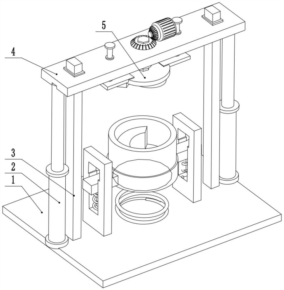
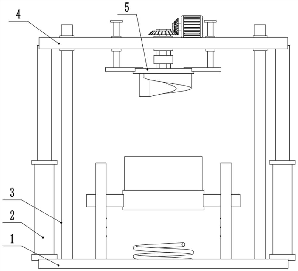
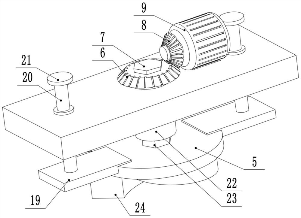
[0030] see Figure 1-8 , a small vortex mill, comprising a base plate 1, the left and right ends of the upper surface of the base plate 1 are provided with support columns 3, the upper part of the support column 3 is slidingly connected to the lifting plate 4, and the upper part of the base plate 1 is provided with a cylinder 2, the cylinder The piston rod of 2 is fixedly connected to the left and right ends of the lifting plate 4, the middle part of the lifting plate 4 is rotatably connected to the first rotating rod 7, the bottom of the first rotating rod 7 is provided with a grinding plate 5, and the bottom of the grinding plate 5 is provided with an upper Grinding head 24. The right side of the upper surface of the lifting plate 4 is provided with a drive motor 9, the output shaft of the drive motor 9 is fixedly connected to the first bevel gear 8, the first bevel gear 8 is meshed with the second bevel gear 6, and the second bevel gear 6 is fixedly connected The upper end...

Embodiment 2

[0033] see Figure 7 , the other content of this embodiment is the same as that of Embodiment 1, the difference is that: the top of the first chute 12 is provided with a second chute 15, and the internal size of the second chute 15 is greater than the cross-sectional size of the sliding rod 14 . In order to facilitate the removal of the product from the grinding tube 17, a second chute 15 with a larger size is arranged on the upper part of the first chute 12. After the device finishes grinding, the whole device can be raised so that the sliding rod 14 slides into the In the second chute 15, the slide bar 14 can rotate in the second chute 15 at this time, so that the grinding tube 17 is tilted forward, so that the material inside the grinding tube 17 falls to realize the effect of unloading.

[0034] During the implementation of the present invention, the cylinder 2 is started, and the piston rod of the cylinder 2 is stretched out, so that the grinding plate 5 moves upwards. A...


PUM


Abstract

The invention relates to the technical field of grinding, and discloses a vortex type small-sized pulverizer. The vortex type small-sized pulverizer comprises a bottom plate; supporting columns are arranged at the left end and the right end of the upper surface of the bottom plate; the upper portions of the supporting columns are slidably connected with a lifting plate; an air cylinder is arranged on the upper portion of the bottom plate; a piston rod of the air cylinder is fixedly connected with the left end and the right end of the lifting plate; the middle of the lifting plate is rotationally connected with a first rotating rod; a grinding plate is arranged on the lower portion of the first rotating rod; an upper grinding head is arranged on the lower portion of the grinding plate; supporting plates are arranged on the left side and the right side of the upper surface of the bottom plate; first sliding grooves are formed in the lower portions of the supporting plates; the middles of the first sliding grooves are slidably connected with the middles of sliding rods; and the ends, close to the center of the device, of the two sliding rods are fixedly connected with the left side and the right side of a supporting plate, and a grinding pipe is arranged on the outer side of the upper surface of the supporting plate. According to the vortex type small-sized pulverizer, materials are ground through the upper grinding head and a lower grinding head which are provided with vortex structures.

Description

technical field [0001] The invention relates to the technical field of grinding, in particular to a small vortex mill. Background technique [0002] Milling machine, also known as milling machine, is a kind of mining equipment. Grinding machines can be divided into ball mills, column mills, rod mills, tube mills, autogenous mills, rotary mortar roller mills, vertical mills, multi-layer vertical mills and vertical mills according to different grinding media and grinding materials. roller mill etc. [0003] The pulverizer usually uses two grinding devices to rotate relative to each other to achieve relative displacement, so that the material can be ground between the two grinding devices. However, when the pulverizer is working, the material with large particles will move to the side of the device. At the corners, the overall grinding effect is mediocre, so it needs to be improved. Contents of the invention [0004] The present invention provides a small vortex mill, whic...

Claims


Application Information

Patent Timeline
IPC IPC(8): B02C19/00B02C23/00
CPCB02C19/00B02C23/00
Inventor 陈希福
Owner 新乡汇淼科技有限公司
Why Eureka
Try Eureka