High-stability fixing clamp for machining

A technology for machining and fixing fixtures, which is applied in the direction of manufacturing tools, workpiece clamping devices, cleaning methods and appliances, etc., can solve the problems of reducing workpiece processing accuracy, workpiece processing influence, and poor clamping effect, so as to improve processing efficiency, Easy to clamp and fix, improve the effect of stability

Active Publication Date: 2021-06-04
新乡市亚联重工有限公司
View PDF7 Cites 4 Cited by
  • Summary
  • Abstract
  • Description
  • Claims
  • Application Information

AI Technical Summary

Problems solved by technology

[0002] Machining is the process of changing the shape, size, position and nature of the workpiece to make it a finished product or semi-finished product. According to the processing method, it can be divided into cutting processing and pressure processing. When processing raw materials or semi-finished products, in order to ensure the processing accuracy and Processing efficiency, usually use fixtures to fix workpieces or semi-finished products. Fixtures are devices used to quickly, conveniently and safely install workpieces. When existing fixtures clamp workpieces, their clamping effect is poor and cannot Adjust the clamping length of the workpiece according to the needs, which reduces the machining accuracy of the workpiece. When the specification of the workpiece is small, the traditional clamp has a large volume, which will affect the processing of the workpiece.

Method used


Image

  • High-stability fixing clamp for machining
  • High-stability fixing clamp for machining
  • High-stability fixing clamp for machining

Examples


Embodiment approach

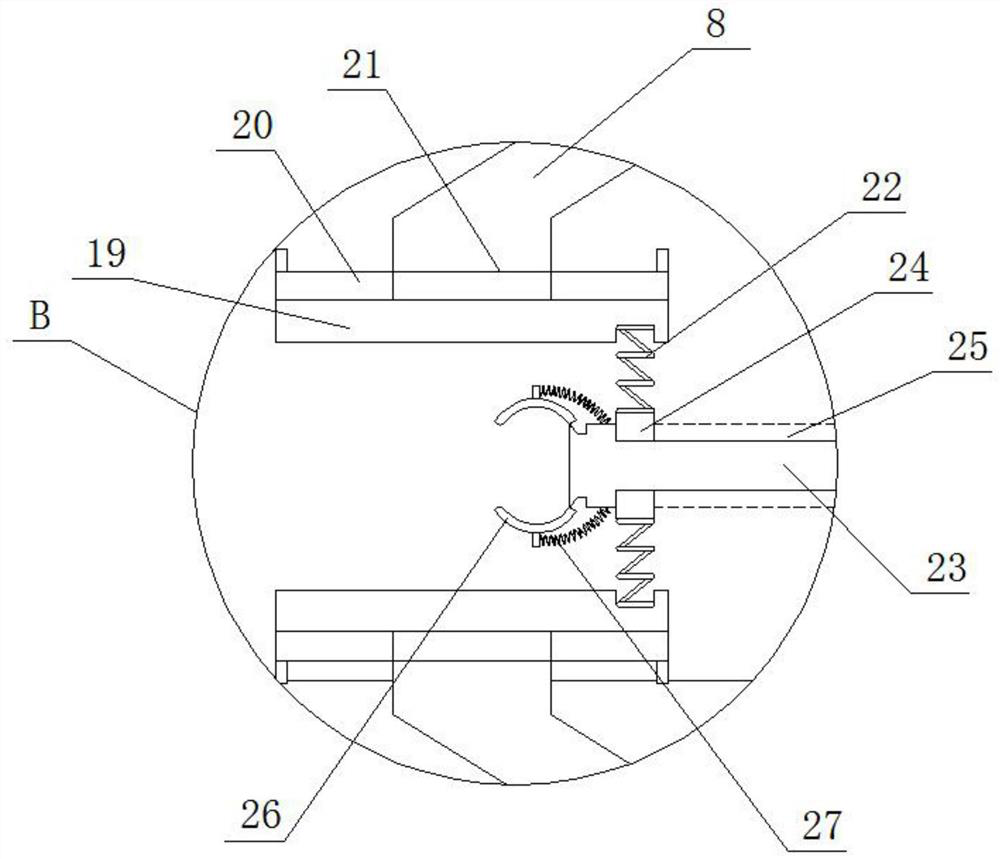
[0030] As a preferred embodiment of the present invention, the two ends of the splint slider 20 are provided with limiting plates, and the splint slider 20 is slidably arranged inside the splint chute 21, and the splint slider 20 and the splint chute The shapes of 21 are all "T" shapes, which can limit the clamping plate 19 and facilitate the sliding of the clamping plate 19 at one end of the fixed cover plate 8 .

[0031] As a preferred embodiment of the present invention, the shape of the fixed rod slider 24 and the fixed rod chute 25 is "T" shape, which can limit the fixed rod slider 24, so that the fixed rod slider 24 is convenient for fixing. Slide on rod 23.

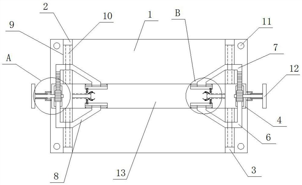
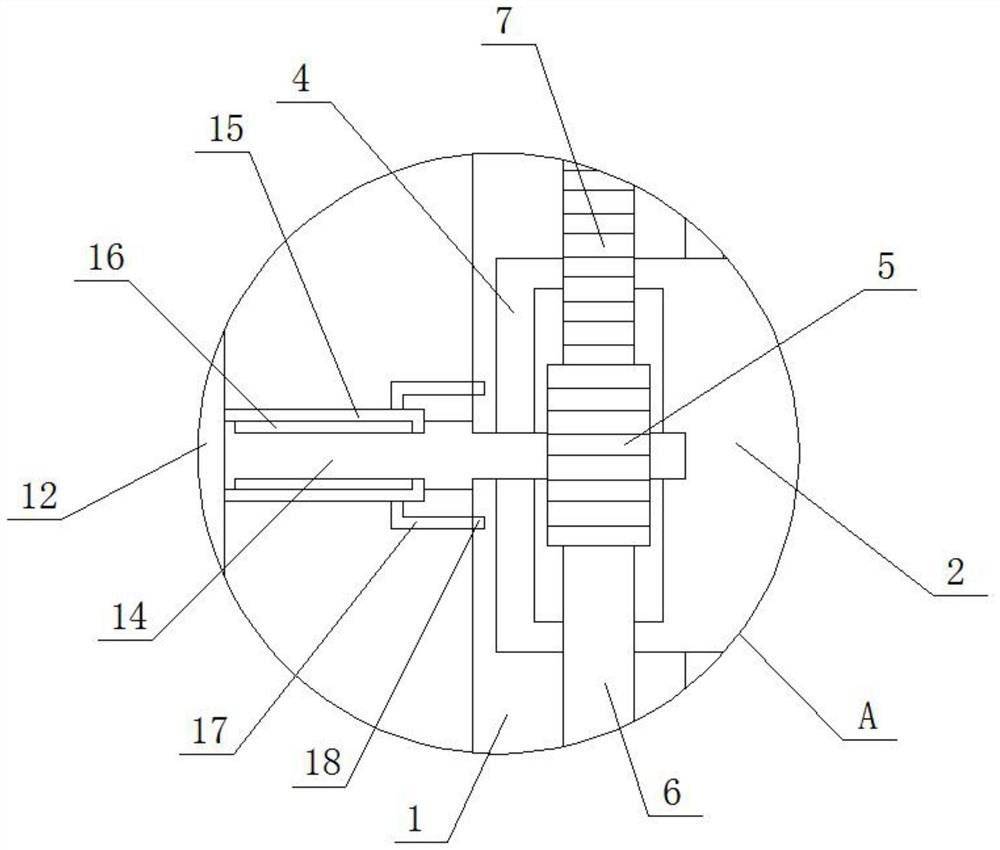
[0032] As a preferred embodiment of the present invention, the two racks and gears 5 mesh with each other and are arranged in parallel to facilitate transmission and adjust the upper support rod 6 and the lower support rod 7 .

[0033] As a preferred embodiment of the present invention, both the inner side of the sp...


PUM


Abstract

The invention provides a high-stability fixing clamp for machining. The fixing clamp comprises a base, a moving plate, an adjusting plate, a storage box, an upper supporting rod, a lower supporting rod, a fixing plate, a clamping plate, a fixing rod, a cleaning plate and a clamping rod, wherein a base sliding groove is formed in the center of the top of the base, a screw rod is rotationally installed in the base sliding groove, a bottom hand wheel is welded to one end of the screw rod, the moving plate is movably installed on the screw rod through a sliding block, the sliding block is movably installed in the base sliding groove, and the adjusting plate is movably installed on one side of the top of the base through a rotating shaft. According to the high-stability fixing clamp for machining, the clamping length of a workpiece can be adjusted through the clamping plate and the fixing rod according to the specification of the workpiece, the stability of the clamp can be improved through the combined action of an arc-shaped clamping plate, the fixing rod and the clamping plate, the workpiece with the smaller specification can be conveniently machined through adjustment of the adjusting plate, and the workpiece machining efficiency can be improved.

Description

technical field [0001] The invention relates to the technical field of machining fixtures, in particular to a fixture with high stability for machining. Background technique [0002] Machining is the process of changing the shape, size, position and nature of the workpiece to make it a finished product or semi-finished product. According to the processing method, it can be divided into cutting processing and pressure processing. When processing raw materials or semi-finished products, in order to ensure the processing accuracy and Processing efficiency, usually use fixtures to fix workpieces or semi-finished products. Fixtures are devices used to quickly, conveniently and safely install workpieces. When existing fixtures clamp workpieces, their clamping effect is poor and cannot The clamping length of the workpiece is adjusted according to the needs, which reduces the processing accuracy of the workpiece. When the specification of the workpiece is small, the traditional clam...

Claims


Application Information

Patent Timeline
Patent Type & Authority Applications(China)
IPC IPC(8): B25B11/00B08B1/00
CPCB25B11/00B08B1/00
Inventor 汪飞跃
Owner 新乡市亚联重工有限公司
Why Eureka
Try Eureka