
Active pressure applying type gapless sliding block expansion joint device for suspension type monorail track beam

A technology of expansion joints and track beams, which is applied in the direction of tracks, roads, bridges, etc., can solve the problems of track beams being prone to bangs and loud noises, achieve good adaptability and reliability, reduce wheel wear, improve stability and The effect of comfort

Pending Publication Date: 2021-06-04
CHINA RAILWAY SIYUAN SURVEY & DESIGN GRP
View PDF0 Cites 0 Cited by
  • Summary
  • Abstract
  • Description
  • Claims
  • Application Information

AI Technical Summary

Problems solved by technology

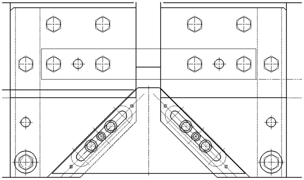
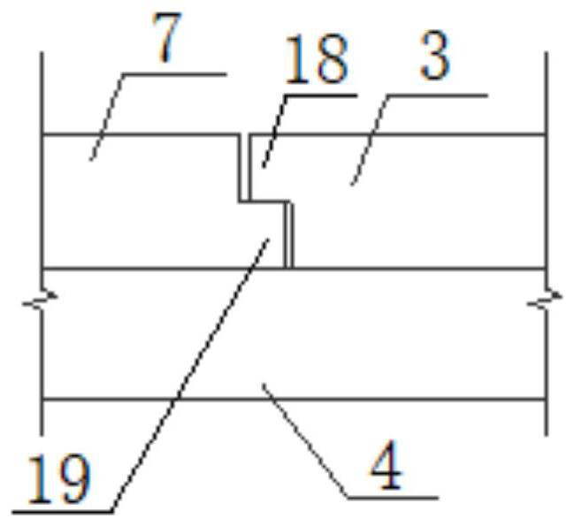
[0005] The gapless slider expansion joint device first appeared in Germany, see Figure 1a , Figure 1b , it slides through the mutual engagement of the trapezoidal sliding plate and the oblique slideway of the fixed plate (see Figure 1b part A, they each have bosses extending into each other’s notch) to drive the trapezoidal sliding plate to slide when the beam body stretches longitudinally, and to maintain a seamless state within the wheel travel range of the suspended monorail train. This technology theoretically It is very ingenious, but in actual engineering, it is strictly restricted by the accuracy of the sliding surfaces of the parts that are occluded. The corner of the beam end of the track beam is poor. On the contrary, when the tolerance is too large, the track beam is easy to rattle and make a lot of noise.

Method used


Image

  • Active pressure applying type gapless sliding block expansion joint device for suspension type monorail track beam
  • Active pressure applying type gapless sliding block expansion joint device for suspension type monorail track beam
  • Active pressure applying type gapless sliding block expansion joint device for suspension type monorail track beam

Examples


Embodiment Construction

[0028] In order to make the object, technical solution and advantages of the present invention clearer, the present invention will be further described in detail below in conjunction with the accompanying drawings and embodiments. It should be understood that the specific embodiments described here are only used to explain the present invention, not to limit the present invention. In addition, the technical features involved in the various embodiments of the present invention described below can be combined with each other as long as they do not constitute a conflict with each other.

[0029] refer to Figure 2 to Figure 7 , a suspension type monorail track beam 1 active pressure type gapless slider expansion joint device, the suspension type monorail track beam 1 includes a top plate, a web 2 and a bottom plate 3, and the web 2 is vertically arranged on the Between the top plate and the bottom plate 3, the gapless slider expansion joint device includes a trapezoidal sliding ...


PUM


Abstract

The invention discloses an active pressure applying type gapless sliding block expansion joint device for a suspension type monorail track beam, the suspension type monorail track beam comprises a top plate, a web plate and a bottom plate, and the gapless sliding block expansion joint device comprises a trapezoidal sliding plate, a lower plate and a spring mechanism. The trapezoid sliding plate is integrally in an isosceles trapezoid shape and arranged between the bottom plates on the two sides of the expansion joint, and the trapezoid sliding plate is connected through the lower plate. The trapezoidal sliding plate is arranged in a notch in the end of the bottom plate, and the bottom plate is provided with an inclined sliding way making contact with the bevel edge of the trapezoidal sliding plate, so that sliding connection is achieved through the inclined sliding way and the bevel edge of the movable plate. And the spring mechanism is used for pressing each bevel edge of the trapezoidal sliding plate on the oblique slide way on the corresponding side all the time, so that the trapezoidal sliding plate moves along with the change of the width of the expansion joint. The driving face is smoother, potholes caused by gaps can be almost eliminated, noise can be effectively reduced, the expansion joint with the large application range can be effectively reduced, and steel can be saved.

Description

technical field [0001] The invention belongs to the field of suspended monorails, and more specifically relates to a suspension-type monorail track beam active pressure-type gapless slider expansion joint device. Background technique [0002] Suspension monorail is a type of monorail, characterized by the use of only one track instead of the two balanced rails of traditional railways. Similar to urban rail transit systems, monorails are mainly used in densely populated cities to carry passengers. [0003] The suspended monorail track beam is a key component of the suspended monorail transportation system. It provides load for the suspended monorail train and bears complex tensile force, compression force, bending force, shear force and torsion force, and requires high Anti-deformation and fracture resistance. [0004] The bottom plate of the track beam is directly used as the sliding surface of the vehicle. Under the action of temperature, braking force and other loads, th...

Claims


Application Information

Patent Timeline
IPC IPC(8): E01B25/22E01B25/24E01D19/06
CPCE01B25/22E01B25/24E01D19/06
Inventor 曾敏文望青饶少臣严爱国马明李元俊刘阳明刘诗文崔旸陈丽莎饶诗维
Owner CHINA RAILWAY SIYUAN SURVEY & DESIGN GRP
Learn More