Rotary jig
a technology of rotary jigs and elongated parts, which is applied in the direction of grinding machines, other manufacturing equipment/tools, applications, etc., can solve the problems of inconvenient detection and remedying of misalignment, inconvenient manufacturing of blades, and inability to meet the needs of grinding, so as to reduce the wear of grinding wheels and increase production capacity
- Summary
- Abstract
- Description
- Claims
- Application Information
AI Technical Summary
Benefits of technology
Problems solved by technology
Method used
Image
Examples
first embodiment
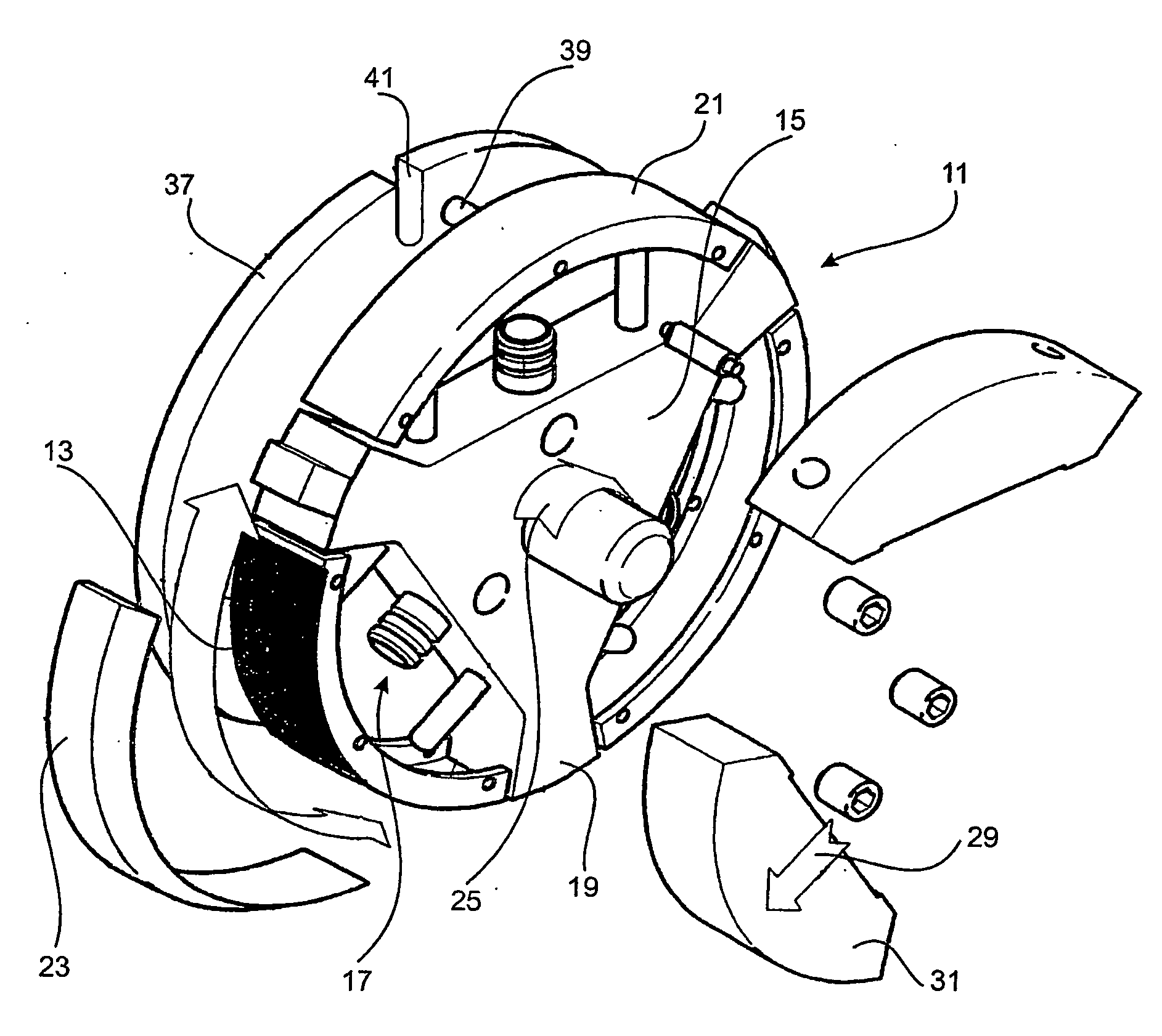
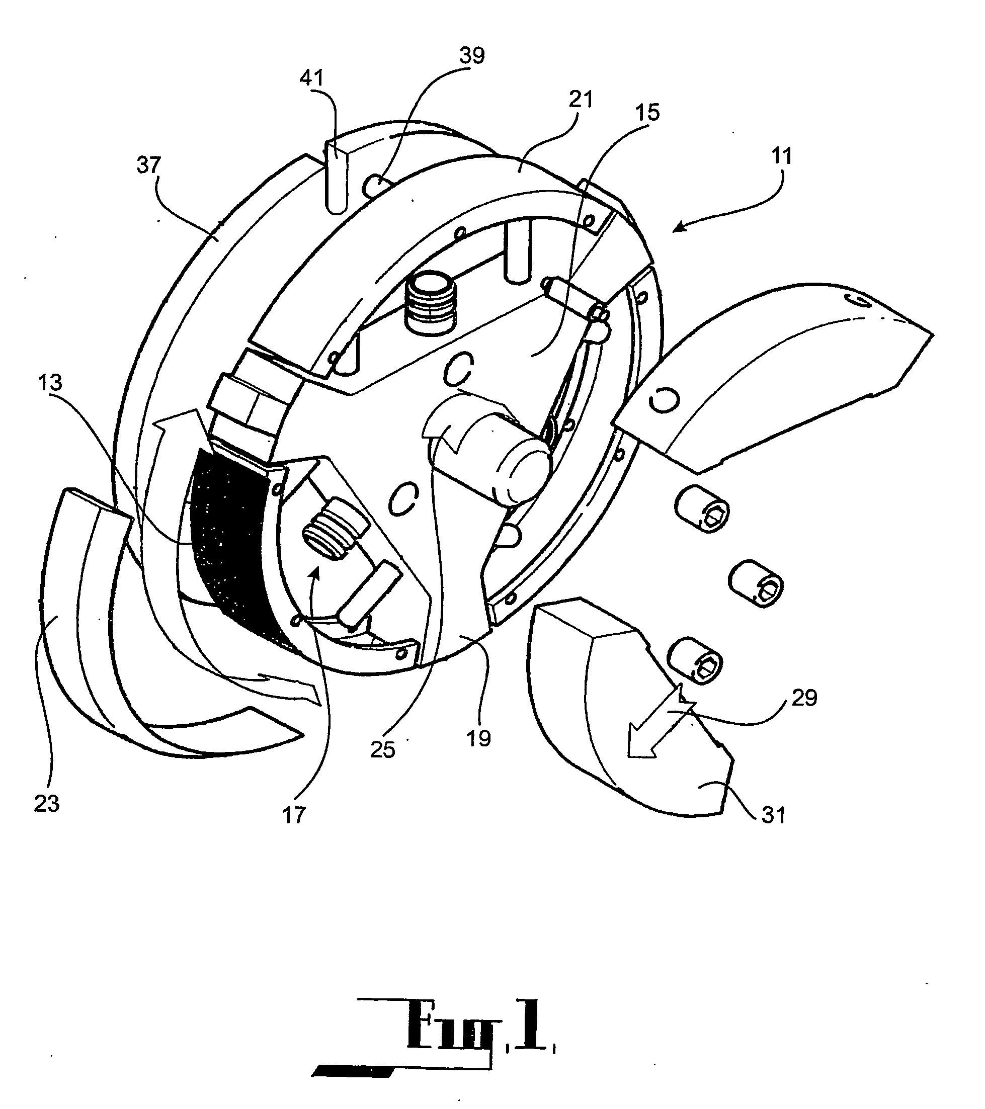
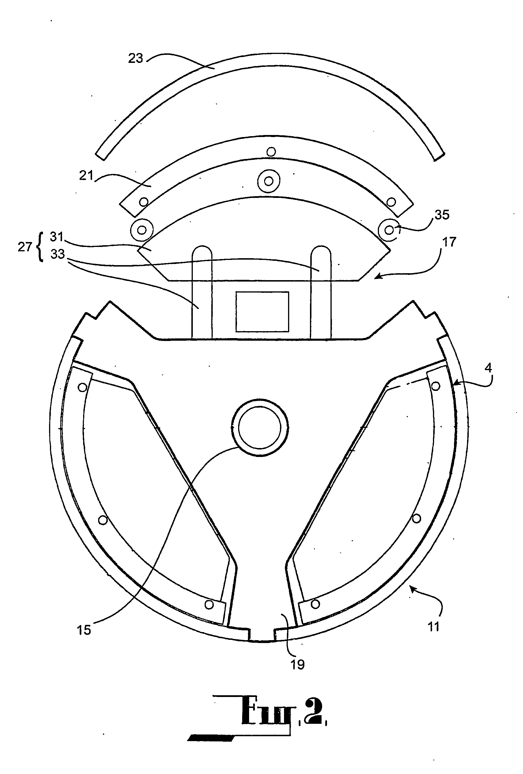
[0058] The first embodiment as shown in FIGS. 1 to 7 is directed to a rotary jig 11 for holding tubes 13, of which at least one of the axial ends are to be ground to form hypodermic needles or blades.
[0059] The rotary jig 11 comprises a central rotary support or mandrel 15 having three angularly displaced clamping sections 17 defined between three equally spaced radially extending arms 19. Each clamping section comprises an inner 21 and outer clamping shoe 23 with opposed arcuate clamping surfaces concentric with the axis of rotation (indicated by the arrow 25) of the mandrel 15, and a clamping mechanism 27 actuable to displace the inner clamping shoe 21 radially outwardly (indicated by the arrow 29) and inwardly relative to the outer clamping shoe 23. As shown, each clamping mechanism 27 comprises a clamping plate 31, actuators 33 for displacing the clamping plate 31 radially outwardly and inwardly relative to the axis of rotation of the mandrel 15, and rollers 35 at the outer arcu...
second embodiment
[0103] The second embodiment as shown in FIGS. 20 and 21 is directed to a rotary jig 211 which can be utilised in the manufacture of hypodermic needles and the like and in particular the machining and finishing of the pointed ends of those needles.
[0104] The embodiment comprises a generally cylindrically shaped body 215 which is supported from a drive shaft 214. The outer perimeter of the body 215 is generally of a cylindrical form and is defined by a set of stations which are located at angularly spaced intervals around the perimeter and which each comprise a clamping section 217 for the tubes 213 which are received in a recess 218 provided at the respective clamping section 217.
[0105] Each clamping section 217 comprises outer fixed clamping shoe 223 which is fixed to the mandrel 215 at the outer-most radial portion of the recess 218 and which when fixed to the mandrel 215 defines a portion of the outer most perimeter of the mandrel 215. The outer clamping shoe 223 is supported fr...
third embodiment
[0114] The third embodiment as shown at FIGS. 22 to 24 comprises a rotary jig 311 for holding tubes 313, of which at least one of the axial ends are to be ground to form hypodermic needles or blades.
[0115] The rotary jig 311 has a triangular shaped perimeter providing three angularly displaced clamping sections 317. The jig comprises a central mandrel 315 having a set of equi-angularly displaced arms 320. Each face of the jig is defined by a clamping section 317 which extends between the arms 320 and each comprise an inner clamping shoe 321 and outer clamping shoe 323 with opposed parallel clamping surfaces which are parallel with the axis of rotation of the mandrel 315, and a clamping mechanism (not shown) supported from the mandrel which is actuable to displace the inner clamping shoe 321 radially outwardly and inwardly relative to the outer clamping shoe 323. The three outer clamping shoes 323 extend between the ends of three radially extending arms 320 of the mandrel 315 and may...
PUM
| Property | Measurement | Unit |
|---|---|---|
| length | aaaaa | aaaaa |
| relative displacement | aaaaa | aaaaa |
| clamping pressure | aaaaa | aaaaa |
Abstract
Description
Claims
Application Information
 - R&D
- Intellectual Property
- Life Sciences
- Materials
- Tech Scout
- Unparalleled Data Quality
- Higher Quality Content
- 60% Fewer Hallucinations
Browse by: Latest US Patents, China's latest patents, Technical Efficacy Thesaurus, Application Domain, Technology Topic, Popular Technical Reports.
© 2025 PatSnap. All rights reserved.Legal|Privacy policy|Modern Slavery Act Transparency Statement|Sitemap|About US| Contact US: help@patsnap.com


