Concrete pouring device

A technology of concrete and pouring pipes, which is applied in the fields of construction, building structure, and building materials, which can solve the problems of unfavorable concrete air bubbles being completely discharged, poor concrete pouring effect, etc., and achieve good vibration effect and good adaptability

Inactive Publication Date: 2021-06-04
王要磊
View PDF5 Cites 0 Cited by
  • Summary
  • Abstract
  • Description
  • Claims
  • Application Information

AI Technical Summary

Problems solved by technology

[0005] Aiming at the deficiencies of the prior art, the present invention provides a concrete pouring device, which solves the problem that the current concrete is usually vibrated after the pouring is completed. This method has a certain delay, which is not conducive to the air bubbles inside the concrete. Completely discharged, making the pouring effect of concrete poor

Method used


Image

  • Concrete pouring device
  • Concrete pouring device
  • Concrete pouring device

Examples


Embodiment 1

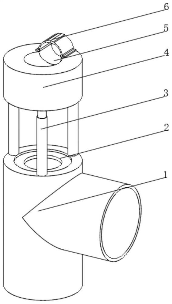
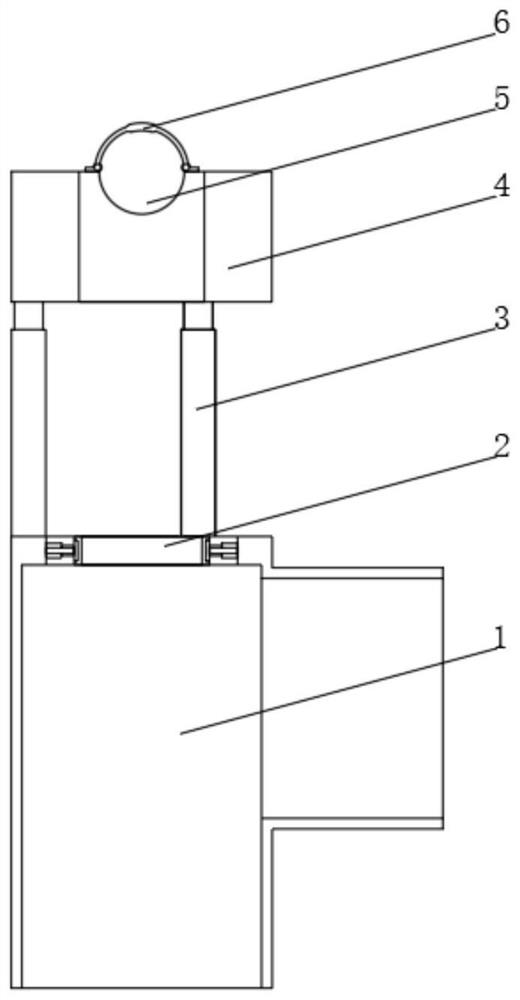
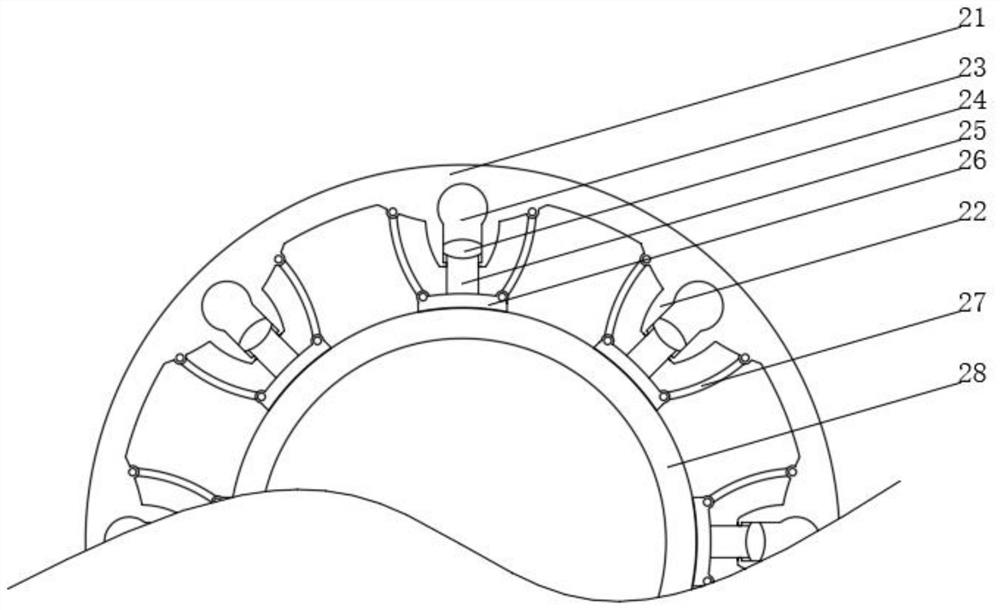
[0032] see Figure 1-4 , the present invention provides a technical solution: a concrete pouring device, comprising a pouring pipe 1, the top inner wall of the pouring pipe 1 is fixedly connected with a fastening device 2, the top of the pouring pipe 1 is fixedly connected with a telescopic rod 3, and the top of the telescopic rod 3 is fixedly connected There is a fixed sleeve 4, the top of one side of the fixed sleeve 4 is provided with a placement groove 5, and the parts of the top of the fixed sleeve 4 located on both sides of the placement groove 5 are rotatably connected with a locking device 6, and the fastening device 2 includes a fastening ring 21 , the inner wall of the fastening ring 21 is fixedly connected with a buffer seat 22, the buffer seat 22 is provided with a buffer cavity 23, the inner wall of the buffer cavity 23 is slidingly connected with a buffer piston head 24, and one side of the buffer piston head 24 is fixedly connected with a piston rod 25, The end ...

Embodiment 2

[0035] see Figure 1-5 , on the basis of Embodiment 1, the present invention provides a technical solution: the locking device 6 includes a fixed plate 61, one end of the fixed plate 61 is rotatably connected to an arc-shaped clamping plate 62, and the end of the arc-shaped clamping plate 62 away from the fixed plate 61 is fixed Connected with a spring catch 63, the inner wall of the arc-shaped clamping plate 62 is provided with an arc-shaped limiting groove 64, and the inner wall of the arc-shaped limiting groove 64 is slidably connected with an arc-shaped spring 65, and the arc-shaped spring 65 is close to the arc-shaped clamping plate 62 One side of the shaft is connected with a threaded push rod 67 through the rotation seat 66. When the flexible shaft of the vibrator needs to be fixed inside the placement groove 5, the flexible shaft is placed inside the placement groove 5, and then the arc-shaped clamping plate 62 is rotated and passed The spring catch 63 locks the arc cl...


PUM


Abstract

The invention discloses a concrete pouring device, and relates to the technical field of concrete pouring. The concrete pouring device comprises a pouring pipe, a fastening device is fixedly connected to the inner wall of the top of the pouring pipe, telescopic rods are fixedly connected to the top of the pouring pipe, a fixing sleeve is fixedly connected to the tops of the telescopic rods, a placing groove is formed in the top of one side of the fixing sleeve, the parts, located on the two sides of the placing groove, of the top of the fixing sleeve are rotationally connected to locking devices correspondingly, each fastening device comprises a fastening ring, the inner wall of each fastening ring is fixedly connected to a buffering base, a buffering cavity is formed in each buffering base, the inner wall of each buffering cavity is slidably connected to a buffering piston head, and one side of each buffer piston head is fixedly connected to a piston rod. The invention relates to the technical field of concrete pouring. According to the concrete pouring device, concrete can be conveniently vibrated while pouring is conducted through the pouring pipe, bubbles can be favorably and rapidly discharged, the vibration effect is better, and the height of a vibrator inside the pouring pipe can be conveniently adjusted.

Description

technical field [0001] The invention relates to the technical field of concrete, in particular to a concrete pouring device. Background technique [0002] Concrete refers to the artificial stone made of cement as the main cementitious material, mixed with water, sand, stones, chemical admixtures and mineral admixtures when necessary, mixed in appropriate proportions, uniformly stirred, compacted and cured. [0003] At present, the concrete is usually vibrated after the pouring is completed. This method has a certain delay, which is not conducive to the complete discharge of air bubbles inside the concrete, making the pouring effect of the concrete poor. Contents of the invention [0004] (1) Solved technical problems [0005] Aiming at the deficiencies of the prior art, the present invention provides a concrete pouring device, which solves the problem that the current concrete is usually vibrated after the pouring is completed. This method has a certain delay, which is no...

Claims


Application Information

Patent Timeline
Patent Type & Authority Applications(China)
IPC IPC(8): E04G21/04
CPCE04G21/0418
Inventor 王要磊
Owner 王要磊
Why Eureka
Try Eureka